
Test reactor NPT 8929
Single-phase test reactor Description These chokes are used as load chokes in testing laboratories. They can be interconnected (almost) arbitrarily. If these chokes are used with appropriate resistors, testing under various cos(phi) is possible. This is required, for example, to test the connection and switching behavior of components Benefits Robust design High flexibility compact design Low losses Technical data Insulation class: F at 40° C Climatic category: 25/085/21 DIN IEC 68 Part 1 Max. winding temperature: 125° C Protection class: IP00 Nominal Voltage: 230 V Rated current: 0,5 – 32,5 A Inductance: 0,127 – 3180 mH Type Rated voltage [V] Rated current [A] Inductance [mH] DC-Resistance [mΩ] Power loss [W] NPT 8929 / 0,5 230 0,5 3180 55670,2 23 NPT 8929 / 1,25 230 1,25 1270 16880,0 43 NPT 8929 / 1,66 230 1,66 955 9977, 8 47 NPT 8929 / 2,5 230 2,5 636 6388,5 66 NPT 8929 / 5 230 5,0 318 1782,5 94 NPT 8929 / 32,5 230 32,5 0,318 0,0 39 NPT 8929 / 32,5 230 32,5 0,127 7,0 13 NPT 8929 / 32,5 230 32,5 0,318 0,0 27 Dimensions in MM Type L [mm] B [mm] H [mm] N1 [mm] N2 [mm] øD1 [mm] Connection [mm²] Cooper [kg] Weight [kg] NPT 8929 / 0,5 120 96 205 76 77 7 x 13 2,5 0,7 5 NPT 8929 / 1,25 160 105 265 100 81 7 x 13 2,5 2 9,8 NPT 8929 / 1,66 160 115 270 100 91 7 x 13 2,5 3,1 12,2 NPT 8929 / 2,5 200 122 310 124 94 10 x 18 4 3,9 17 NPT 8929 / 5 240 153 355 144 125 10 x 18 4 7,3 29 NPT 8929 / 32,5 120 96 208 76 77 7 x 13 16 0,84 6,5 NPT 8929 / 32,5 100 82 190 63 65 6 x 10 16 0,44 3,6 NPT 8929 / 32,5 120 96 208 76 77 7 x 13 16 0,94 6,5
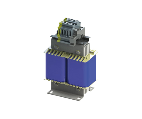
Test Choke NPT 892
Single-Phase DC Test Choke Description Switches must pass many different tests during the approval phase. Some of these tests concern switching behavior under various load conditions; the switch is tested at nominal load, overload, and various power factors. In addition to continuous load, switch-on and switch-off processes are also examined. During these tests, it is crucial not to change the set parameters throughout the entire test. In the past, air core chokes were used as inductive loads because they almost never saturate. However, air core chokes are larger and have a stronger stray field than comparable iron core chokes with the same magnetic energy. To set the respective cos? value, appropriately adapted Resistors then had to be connected. To meet all required test points, many different inductive and resistive loads had to be available. Benefits Adapted linearity, thus no saturation in the respective operating range multiple taps, only a few Chokes are needed instead of many. Adapted winding resistance, thereby reducing ohmic loads Designed for continuous and short-term load Optimization of weight and dimensions leads to cost reduction High nominal voltage, standard up to 1000V Technical Data Insulation Class: F at 40°C ambient Climatic Category: 25/085/21 DIN IEC 68 Part 1 Max. Winding Temperature: 100°C Protection Class: IP 00 Nominal Voltage: 24 V Nominal Current: 0.2 – 4 A Inductance: 160 – 125000 mH Type Nominal Voltage [V] Nominal Current [A] Inductance [mH] DC Resistance [mΩ] Power Loss [W] NPT 892/0.2 24 50/60 Hz 0,2 125.000 197,3 20 NPT 892/2 24 50/60 Hz 2 1.200 2,855 – NPT 892/4 24 50/60 Hz 4 160 2,8 64 Dimensions in MM Type L [mm] B [mm] H [mm] N1 [mm] N2 [mm] øD1 [mm] øD1 [mm] A1 [mm] Copper [kg] Weight [kg] NPT 892/0.2 200 148 261 124 120 10×18 6,2 24 1 2 NPT 892/2 240 168 375 144 140 10×18 18 44 3 10 NPT 892/4 280 173 417 176 143 13×20 4,4 38 11 38
Mains chokes N CNW 905
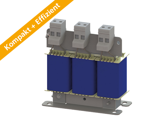
Three-phase line reactor 2% Uk Description Compact & Efficient The new series not only scores points for its faster delivery time, but also for its resource conservation and increased efficiency. Power Noise Reduction – save up to 15% energy costs. A line reactor relieves the supply network by compensating the harmonics reactive power. The harmonics and commutation notches are reduced strongly. By using a line reactor the inverter electronics and DC-capacitors will be protected. Starting currents and current peaks are reduced up to 30%. Mains chokes help to comply with the international PowerQuality standards IEEE 519 or EN 61000-3-2. Benefits compact design extended service life for electrical consumers Low-temperature rise Attenuation of current spikes up to 30% Reduction of input current up to 15% Low-noise Production according to UL insulation system E251513 possible Typical applications Drive systems for motor drives: Mechanical engineering, Elevators / escalators, Pipes, Conveyor technology, Ventilation and air conditioning, Robotics, Automation technology, Power supplies and Wind turbines Technical data Rated voltage: U ≤ 3 x 500 V Short circuit: Uk 2% (400VAC/50Hz, INenn) Frequency: 50/60 Hz According to: EN 60289 / EN 61558 Test voltage: LL 2500 V, DC 1min; L-PE 2500 V, DC 1min Insulation class: T40/F Protection class: IP00 Climate category: DIN IEC 60068-1 Overload: 1.5 x INominal 1 min / h Design: standing on foot bracket Technical data Type Nominal voltage / nominal frequency UN [V] Nominal current IN [A] Inductance L [mH] Losses P [W Weight [kg Mass Cu [kg] Mass Al [kg] N CNW 903 /3 500 50 / 60 Hz 3 9,800 16 1.0 0.2 – N CNW 903 /6 500 50 / 60 Hz 6 4,880 25 2.0 0.3 – N CNW 903 /8 500 50 / 60 Hz 8 3,680 35 2.0 0.3 – N CNW 903 /10 500 50 / 60 Hz 10 2,930 36 3.0 0.4 – N CNW 903 /12 500 50 / 60 Hz 12 2,450 38 3.0 0.45 – N CNW 903 /16 500 50 / 60 Hz 16 1,830 48 4.0 0.7 – N CNW 903 /25 500 50 / 60 Hz 25 1,170 63 5.2 0.8 – N CNW 903 /36 500 50 / 60 Hz 36 0,810 67 7.0 1.9 – N CNW 903 /50 500 50 / 60 Hz 50 0,590 112 9.0 1.2 – N CNW 903 /70 500 50 / 60 Hz 70 0,420 180 11 2.1 – N CNW 903 /90 500 50 / 60 Hz 90 0,330 144 17 2.5 – N CNW 903 /110 500 50 / 60 Hz 110 0,270 179 18 1.8 – N CNW 903 /125 500 50 / 60 Hz 125 0,235 220 17 2.6 – N CNW 903 /160 500 50 / 60 Hz 160 0,180 145 22 5.0 – N CNW 903 /200 500 50 / 60 Hz 200 0,147 187 26 1.3 3.8 N CNW 903 /250 500 50 / 60 Hz 250 0,118 254 35 1.3 3.0 N CNW 903 /300 500 50 / 60 Hz 300 0,098 250 37 1.3 4.7 N CNW 903 /350 500 50 / 60 Hz 350 0,084 267 45 2.6 5.0 N CNW 903 /400 500 50 / 60 Hz 400 0,074 365 52 2.6 5.2 N CNW 903 /500 500 50 / 60 Hz 500 0,059 423 58 2.9 7.8 N CNW 903 /600 500 50 / 60 Hz 600 0,049 450 71 5.0 6.9 N CNW 903 /700 500 50 / 60 Hz 700 0,042 493 88 5.0 9.2 N CNW 903 /800 500 50 / 60 Hz 800 0,037 545 96 5.1 8.3 N CNW 903 /900 500 50 / 60 Hz 900 0,033 655 108 12.5 10.1 N CNW 903 /1000 500 50 / 60 Hz 1000 0,029 775 108 12.5 10.1 N CNW 903 /1200 500 50 / 60 Hz 1200 0,024 1009 133 13.9 12.4 Dimensions in mm Type Length L1 (mm) Lenght L2 (mm) Width B1 (mm) Width B2 (mm) High max. H1 (mm) Mounting N1 (mm) Mounting N2 (mm) Mounting D1 (mm x mm) Terminal/ Cable lug [mm²] Angle [mm x mm] Connection A1 (mm) Connetion D2 (mm) PE N CNW 903 /3 65 78 50 60 95 50 38 5 x 8 2.5 M4 N CNW 903 /6 80 96 55 65 110 56 43 5 x 8 2.5 M4 N CNW 903 /8 125 120 61 66 130 100 45 5 x 8 2.5 M4 N CNW 903 /10 125 120 71 76 130 100 55 5 x 8 2.5 M4 N CNW 905 /12 125 120 71 76 130 100 55 5 x 8 2.5 M4 N CNW 903 /16 155 150 76 76 155 130 54 8 x 12 2.5 M4 N CNW 903 /25 155 150 91 101 170 130 69 8 x 12 10 M4 N CNW 903/36 190 180 81 91 195 170 57 8 x 12 10 M6 N CNW 903 /50 190 180 101 111 195 170 77 8 x 12 10 M6 N CNW 903 /70 230 136 200 176 73 9 x 13 16 (M8) 45 M8 N CNW 903 /90 230 150 200 176 95 9 x 13 16 (M8) 45 M8 N CNW 905 /110 240 150 210 185 97 10 x 18 16 (M8) 45 M8 N CNW 905 /125 240 150 210 185 95 10 x 18 45 M8 N CNW 903 /160 240 175 210 185 103 10 x 18 35 (M10) 55 M8 N CNW 903 /200 300 148 270 224 95 10 x 18 30 x 4 39 11 M12 N CNW 903 /250 300 184 270 224 125 10 x 18 30 x 4 39 11 M12 N CNW 903 /300 300 190 270 224 125 10 x 18 30 x 4 39 11 M12 N CNW 903 /350 340 192 305 248 130 10 x 18 40 x 5 49 13 M12 N CNW 903 /400 360 195 315 264 142 10 x 18 40 x 5 49 13 M12 N CNW
Mains choke N CNW 903

Three-phase line reactor 4% Uk Description Compact & Efficient The new series not only scores points for its faster delivery time, but also for its resource conservation and increased efficiency. Reduce mains interference – save up to 20% on energy costs. A mains choke relieves the supply network by compensating for harmonic reactive power. The harmonics and commutation dips are greatly reduced. The use of a mains choke protects the inverter electronics and the DC link capacitors. Starting currents and current peaks are reduced up to 60%. Line reactors help to comply with international power quality standards IEEE 519 or EN 61000-3-2. Benefits compact design extended service life for electrical consumers Low-temperature rise Attenuation of current spikes up to 60% Reduction of input current up to 20% Low-noise Production according to UL insulation system E251513 possible Typical application Drive systems for motor drives, Mechanical engineering, Elevators / escalators, Pipes, Conveyor technology, Ventilation and air conditioning, Robotics, Automation technology, Power supplies, Wind turbines Technical data Rated voltage: U ≤ 3 x 500 V Short circuit: Uk 4% (400VAC/50Hz, INenn) Frequency: 50/60 Hz According to: EN 60289 / EN 61558 Test voltage: L-L 2500 V, DC 1min; L-PE 2500 V, DC 1min Insulation class: T40/F Protection rating: IP 00 Climate category: DIN IEC 60068-1 Overload: 1,5 x INenn 1 min / h Design: standing on foot bracket Technical data Type Nominal voltage / nominal frequency UN [V] Nominal current IN [A] Inductance L [mH] Losses P [W] Mass [kg] Weight Cu [kg Mass Al [kg] N CNW 903 /3 500 50 / 60 Hz 3 9,800 16 1,0 0,2 N CNW 903 /6 500 50 / 60 Hz 6 4,880 25 2,0 0,3 N CNW 903 /8 500 50 / 60 Hz 8 3,680 35 2,0 0,3 N CNW 903 /10 500 50 / 60 Hz 10 2,930 36 3,0 0,4 N CNW 903 /12 500 50 / 60 Hz 12 2,450 38 3,0 0,5 N CNW 903 /16 500 50 / 60 Hz 16 1,830 48 4,0 0,7 N CNW 903 /25 500 50 / 60 Hz 25 1,170 63 5,2 0,8 N CNW 903 /36 500 50 / 60 Hz 36 0,810 67 7,o 1,9 N CNW 903 /50 500 50 / 60 Hz 50 0,590 112 9 1,2 N CNW 903 /70 500 50 / 60 Hz 70 0,420 180 11 2,1 N CNW 903 /90 500 50 / 60 Hz 90 0,330 144 17 2,5 N CNW 903 /110 500 50 / 60 Hz 110 0,270 179 18 2,8 N CNW 903 /125 500 50 / 60 Hz 125 0,235 220 17 2,6 N CNW 903 /160 500 50 / 60 Hz 160 0,180 145 22 5,0 N CNW 903 /200 500 50 / 60 Hz 200 0,147 187 26 1,3 3,8 N CNW 903 /250 500 50 / 60 Hz 250 0,118 254 35 1,3 3,0 N CNW 903 /300 500 50 / 60 Hz 300 0,098 250 37 1,3 4,7 N CNW 903 /350 500 50 / 60 Hz 350 0,084 267 45 2,6 5,0 N CNW 903 /400 500 50 / 60 Hz 400 0,074 365 52 2,6 5,2 N CNW 903 /500 500 50 / 60 Hz 500 0,059 423 58 2,9 7,8 N CNW 903 /600 500 50 / 60 Hz 600 0,049 450 71 5,0 6,9 N CNW 903 /700 500 50 / 60 Hz 700 0,042 493 88 5,0 9,2 N CNW 903 /800 500 50 / 60 Hz 800 0,037 545 96 5,1 8,3 N CNW 903 /900 500 50 / 60 Hz 900 0,033 655 108 12,5 10,1 N CNW 903 /1000 500 50 / 60 Hz 1000 0,029 775 108 12,5 10,1 N CNW 903 /1200 500 50 / 60 Hz 1200 0,024 1009 133 13,9 12,4 DIMENSIONS IN MM Type Length L1 (mm) Lenght L2 (mm) Width B1 (mm) Width B2 (mm) High max. H1 (mm) Mounting N1 (mm) Mounting N2 (mm) Mounting D1 (mm x mm) Terminal/cable lug [mm²] Connection Angle (mm x mm) Connection A1 (mm) Connetion D2 (mm) PE connection N CNW 903 /3 65 78 50 60 95 50 38 5 x 8 2,5 M4 N CNW 903 /6 80 96 55 65 110 56 43 5 x 8 2,5 M4 N CNW 903 /8 125 120 61 66 130 100 45 5 x 8 2,5 M4 N CNW 903 /10 125 120 71 76 130 100 55 5 x 8 2,5 M4 N CNW 903 /12 125 120 71 76 130 100 55 5 x 8 2,5 M4 N CNW 903 /16 155 150 76 76 155 130 54 8 x 12 2,5 M4 N CNW 903 /25 155 150 91 101 170 130 69 8 x 12 10 M4 N CNW 903 /36 190 180 81 91 195 170 57 8 x 12 10 M6 N CNW 903 /50 190 130 160 170 77 8 x 12 16 (M6) 45 M6 N CNW 903 /70 230 136 200 176 73 9 x 13 16 (M8) 45 M8 N CNW 903 /90 230 150 200 176 95 9 x 13 16 (M8) 45 M8 N CNW 903 /110 240 150 210 185 97 10 x 18 16 (M8) 45 M8 N CNW 903 /125 240 150 210 185 95 10 x 18 16 (M8) 45 M8 N CNW 903 /160 240 175 210 185 103 10 x 18 35 (M10) 55 M8 N CNW 903 /200 300 148 270 224 95 10 x 18 30 x 4 39 11 M12 N CNW 903 /250 300 184 270 224 125 10 x 18 30 x 4 39 11 M12 N CNW 903 /300 300 190 270 224 125 10 x 18 30 x 4 39 11 M12 N CNW 903 /350 340 192 305 248 130 10 x 18 40 x 5 49 13 M12 N CNW 903 /400 360 195 315 264 142 10 x 18 40 x 5 49 13 M12 N CNW 903 /500 360 200 345 264