
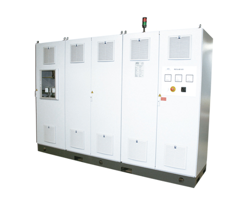
ADJUSTABLE AND CONSTANT VOLTAGE SUPPLY REOLAB 600
Adjustable and constant voltage supplies, Electronic solution Description The three-phase AC power supplies with separate windings include an adjustable variable output voltage and variable output frequency. The AC power supplies are suitable for grid emulation and simulation, as well as for testing devices, components, or systems for 60 Hz grids. They consist of an inverter with adjustable frequency and ensure a clean sinusoidal output waveform with REO sine filters. Benefits All power supplies can optionally be equipped with a computer interface for external operation. Of course, these devices can also be designed with other technical parameters according to customer requirements. Technical Data Input voltage 3 x 400 V L/L or 3 x 230 V L/N Output voltage max. 3 x 0 – 500 VAC Output current 3 x 22 A Output frequency 16 – 1600 Hz variable Output power 19 kVA as standard version Connection group Delta / Star Protection class IP 20 Frequency range 50/60 Hz Data Sheet All data and configurations can be found in our product data sheet. Download Data Sheet
ADJUSTABLE AND CONSTANT VOLTAGE SUPPLY REOLAB 126,127
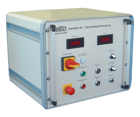
Adjustable and constant voltage supplies, laboratory unit Description Single-phase voltage supplies in autotransformer configuration with motor drive and electronic voltage regulation. Benefits no harmonics no EMC interference clean sinusoidal waveform Technical data* Input voltage 230 VAC or 400 VAC Output voltage 0 – 230 VAC or 0 – 400 VAC Output current 9 – 40 A Output power 2.7 – 16 kVA Circuit Autotransformer Degree of protection IP 20 Control accuracy ± 1% *Of course, other voltages and power ratings can also be offered after consultation. In addition, different operating options/operating concepts and industrial interfaces are possible. Data sheet All data and configurations can be found in our product data sheet. Download data sheet
ADJUSTABLE AND CONSTANT VOLTAGE SUPPLY REOLAB 123, 124
Three-phase AC/DC voltage supplies with separate winding and motor drive Description REOLAB 123 Three-phase AC/DC voltage supplies with separate winding and motor drive for testing/developing, e.g., AC and DC converters or auxiliary power converters. REOLAB 124 Three-phase AC/DC voltage supplies with separate winding and motor drive. Used for motor testing. Benefits no harmonics no EMC interference clean sine wave Technical data REOLAB 123 Input voltage 3 x 400 VAC Output voltage 0 – 2500 V or 0 – 5000 DC or 0 – 430 VAC Output current 60 ADC, 30 ADC, 335 AAC Output power 150 kW as standard version / 144 kVA Switching group Delta / Star / Star / 2 x B6U/li0 Protection class IP 20 Frequency range 50/60 Hz Technical data REOLAB 124 Input voltage 3 x 400 VAC Output voltage 0 – 500 VDC or 3 x 0 – 600 VAC or 0 – 300 DC Output current 200 ADC, 3 x 200 AAC, 15 ADC Output power 100kW as standard version / 208 kVA or 4.5 kW Switching group Star / Star / 2 x B6U Protection class IP 20 Frequency range 50/60 Hz *Of course, other voltages and powers can also be offered upon request. In addition, different operating options/concepts and industrial interfaces are possible. Data sheet All data and configurations can be found in our product data sheet. Download data sheet
ADJUSTABLE AND CONSTANT VOLTAGE SUPPLY REOLAB 128, 129

Adjustable and constant voltage supplies, laboratory unit Description Single-phase voltage supplies with separate winding, motor-driven and with electronic voltage regulation. Benefits no harmonics no EMC interference clean sine wave Technical data* Input voltage 230 VAC or 400 VAC Output voltage 0 – 230 VAC or 0 – 400 VAC Output current 10 – 40 A Output power 2.3 – 16 kVA Circuit separate winding Protection class IP 20 Control accuracy ± 1% *Of course, other voltages and power ratings can also be offered upon request.In addition, different operating options/concepts and industrial interfaces are possible.
Three-phase AC High-Current Power Supply REOLAB 220
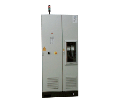
Adjustable and constant high-current power supply for switch test benches Description REO high-current power supplies are used wherever test specimens need to be tested with several thousand amperes. Specifically, these include switchgear, fuses, cables, etc. The test specimens are thermally heated and tested under nominal conditions in continuous tests. Tests with defined overload curves are also performed. Traditional voltage adjustments with variable transformers ensure that the input signal is passed through to the output as a clean sine wave. This allows every test with specimens to be conducted with any current value and in a sinusoidal manner, and to be reproduced at any time. The high-current sources are electronically controlled and can achieve a control accuracy of ( 0.5%) and be integrated into the laboratory network via various BUS systems. Benefits Single- or three-phase high-current power supplies AC power supplies up to 3x 10 kA Modular design of the various modules (control unit, regulation unit, power section) Typical applications Heating tests of components such as cables and contacts, low-voltage distribution, switchgear with low-impedance. Technical data* Input voltage 3 x 400 VAC 50/60 Hz Output voltage 3 x 0-10 V per phase Output current up to 3 x 10,000 A Output power up to 300 kVA Switching group Star/open/open/open Protection class IP 20 *Of course, other voltages and power ratings can also be offered upon request. Furthermore, different operating options/control concepts and industrial interfaces are possible. Datasheet All data and configurations can be found in our product datasheet. Download Datasheet
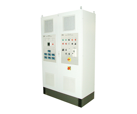
DC Voltage Source REOLAB 420, 520
REO DC high-voltage power supply Description The three-phase DC high-voltage power supply is suitable for the development and testing of frequency converters for railway technology. These are located in development laboratories and test fields, testing institutes, schools and universities. Due to the high DC output voltage, appropriate safety measures have been taken, such as: Emergency stop circuit with external inputs and outputs as two-pole potential-free contacts for emergency stop and safety circuits Warning lights and additional connection options for external warning lights Discharge circuit for the intermediate circuit capacitor Earthing disconnector with pneumatic drive for short-circuiting and earthing the DC output The pneumatic drive short-circuits and grounds the DC output even in the event of a mains voltage failure. Three-phase DC high-voltage power supplies with separate winding, motor drive and electronic voltage regulation of the output voltage to approx. 1.0 %, with short-circuit-proof DC output Benefits compact and modular design (thus easy expansion possible) Control via PowerFormer Hazard assessment according to the Machinery Directive possible special safety circuit no EMC problems Technical data REOLAB 420 Input voltage 3 x 400 V L/L or 3 x 230 V L/N Output voltage 0 – 12000VDC Output current 2 x 20 – 300 A Output power 100 kW – 800 kW as standard Vector group Delta /Star / Star 2 x B6U Degree of protection IP 20 Frequency range 50 / 60 Hz Technical data REOLAB 520 The REOLAB 520 power supplies have the same equipment as the REOLAB 420 DC power supplies, but with an additional separately regulated DC output of 0 – 150 VDC, 30 AC or 50 ADC for the control voltage of the power semiconductors. On request also with built-in UPS, so that the power semiconductors still receive control voltage for a certain period of time even in the event of a power failure. *Of course, other voltages and power ratings can also be offered after consultation. In addition, different operating options/operating concepts and industrial interfaces are possible. Data sheet All data and configurations can be found in our product data sheet. Download data sheet
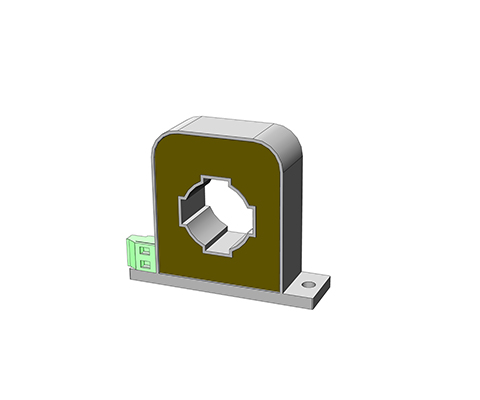
PASSIVE CURRENT TRANSFORMER SERIES IN-I
Pulse Current Transformers Description Due to the selected materials, REO pulse current transformers of the IN-I series can represent current with high accuracy and the corresponding transformation ratio – making them particularly suitable for power measurement, current monitoring and analysis, and for use in solar inverters. They are also ideally suited for use in active filters, as they can be designed for measuring current peaks. The primary current is measured via a current conductor that passes through the closed toroidal core. The magnetic field generated by the current flow through the conductor is absorbed by the toroidal core and, according to the transformation ratio of the secondary winding, generates a smaller current for measurement purposes. This method reduces a high measurement current to a significantly smaller current and additionally separates it from the primary circuit by means of safe galvanic isolation. Benefits Very precise current measurement Class 0.2 Pulse current measurement Low-loss core (core losses <10W/kg at 20kHz/200mT) Housing made of UL VO material (Conductor must be positioned) Diverse applications, e.g., for:Active filters, EMC measurements, and pulse current measurements Typical Applications Measurement and Testing Technology Technical Data Type 50 100 200 Primary current [A] IPN r.m.s 0 – 50 0 – 100 0 – 200 Max. primary current [A] ImaxPN r.m.s ± 60 ± 120 ± 240 Secondary current [mA] IaN r.m.s 0 – 50 0 – 100 0 – 200 Power [VA] Psek 0,5 1,0 1,5 Transformation ratio KN 1: 1000 1000 1000 Burden resistance [Ω] RB 200 100 37,5 Burden voltage [V] URB r.m.s 10 10 7,5 Measurement accuracy 50 Hz [%] FU ± 0.2 ± 0.2 ± 0.2 Ambient temperature [°C] TA -20 to +70 -20 to +70 -20 to +70 Frequency [Hz] f 0.050 to 50 0.050 to 50 0.050 to 50 Insulation test voltage Primary / Secondary / 2 sec [kVac] VP r.m.s 50 Hz 3 3 3 Storage temperature TS -25 to +85 -25 to +85 -25 to +85 Coil resistance RS @ TA = 25°C 11,5 11,5 9 Weight m 0,270 0,270 0,270 Standards EN/IEC 61869-1/2 Tracking resistance Housing / Casting resin 550 / 600M Creepage distance dCp 10 10 10 Clearance distance dCI 9 9 9 Datasheet All data and configurations can be found in our product datasheet. Download Datasheet Certifications
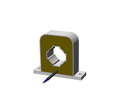
Passive Current Transformers Series IN-D
Differential current transformer Description The residual current transformer makes it possible to measure the residual current on single-phase or three-phase supply cables or individual lines. Both current-carrying conductors (forward and return conductors) are fed through the current opening of the current transformer. The current is measured by comparing the forward and return conductors. Any deviation is displayed at the output of the residual current transformer. Due to the use of highly permeable materials, a typical current deviation from 10 mA is given. The large opening allows the supply lines to pass directly through over a wide area, with the exception of the protective conductor. Due to the high current sensitivity, evaluation in several stages is possible: stage 1: Notice of a malfunction stage 2: Alarm stage 3: Switching off Benefits The measurement from 25 to 400 Hz Nanocrystalline core Transformer for measuring differential current High-quality UL-listed insulating materials (e.g. UL94-V0) Safe electrically isolated primary and secondary circuits Robust housing designs (for horizontal/vertical mounting) Variable connections Wide range of housings with various push-through openings Residual current range 2 – 50 A Typical applications Industry, Renewable energy sources, Metrology and testing techniquesEnergy, automation and building technology Technical data Type 2 4 8 29 30 40 30 40 50 Housing A Housing B Housing C Primary rated current [A] IPN 0,1 – 1 0,1 – 2 0,1 – 4 0,1 – 10 0,1 – 10 0,1 – 10 0,1 – 10 0,1 – 10 0,1 – 10 Max. Primary rated current [A] ImaxPN 2 4 8 20 30 40 30 40 50 Therm. Short-term current ITK 0,5 0,5 0,5 3,6 3,6 3,6 9 9 9 Secondary current [mA] IaN 2 4 4 20 10 5 20 16,67 10 Power [VA] Psek 0,004 0,008 0,016 0,030 0,030 0,015 0,06 0,05 0,06 Ratio KN 500 500 1000 500 1000 2000 500 600 1000 Load resistance [Ω] RB 1000 500 1000 75 300 600 150 180 600 Load voltage [V] URB 2,0 2,0 4,0 1,5 3,0 3,0 3,0 3,0 6,0 Measuring accuracy 50 Hz [%] FU ≤ 1 ≤ 1 ≤ 1 ≤ 1 ≤ 1 ≤ 1 ≤ 1 ≤ 1 ≤ 1 Ambient temperature [°C] TA -10 to +50 -10 to +50 -10 to +50 -10 to +50 -10 to +50 -10 to +50 -10 to +50 -10 to +50 -10 to +50 Frequency range [Hz] f 25 to 400 25 to 400 25 to 400 25 to 400 25 to 400 25 to 400 25 to 400 25 to 400 25 to 400 Insulation test voltagePrimary / Secondary /2 sec [kVac] VP 3 3 3 3 3 3 3 3 3 Connection A Flat 6.3 x 0.8 / plug-in connectionMKS 1853 / terminal 1.5 mm² Storage temperature TS -25 to +85 -25 to +85 -25 to +85 -25 to +85 -25 to +85 -25 to +85 -25 to +85 -25 to +85 -25 to +85 Coil resistance RS 11 11 46 4,5 19 65 5,5 6,5 21 Weight m 0,068 0,068 0,070 0,278 0,278 0,290 0,280 0,280 0,290 Standards EN/IEC 61869-1/2 tracking resistance CTI Housing / cast resin 550/660M or 400/600M Creepage distance dCp 18 18 18 8 8 8 18 18 18 Air distance dCI 16 16 16 7 7 7 16 16 16 Dimensions in MM Type Housing PIN connection [mm²] h [mm] b1/b2 [mm] t [mm] DL/DL1 [mm] FS [mm] p/s [mm] a [mm] c [mm] f [mm] e [mm] l [mm] IN-D / 2 A 1 – 2 38 38/54 20 13 / – 6,3 x 0,8 – 30 47 4,8 – 9 IN-D / 4 A 1 – 2 38 38/54 20 13 / – 6,3 x 0,8 – 30 47 4,8 – 9 IN-D / 8 A 1 – 2 38 38/54 20 13 / – 6,3 x 0,8 – 30 47 4,8 – 9 IN-D / 20 B MKS1853 55 50/68 26 20,2 / – – 45 / 45 60 13 4,3 6 x 4,0 23 IN-D / 30 B MKS1853 55 50/68 26 20,2 / – – 45 / 45 60 13 4,3 6 x 4,0 23 IN-D / 40 B MKS1853 55 50/68 26 20,2 / – – 45 / 45 60 13 4,3 6 x 4,0 23 IN-D / 30 C Clamp 83 100/70 28 35 / 38 – 86 / – 14 – 7 – – IN-D / 40 C Clamp 83 100/70 28 35 / 38 – 86 / – 14 – 7 – – IN-D / 30 C Clamp 83 100/70 28 35 / 38 – 86 / – 14 – 7 – – Data sheet All data and configurations can be found in our product data sheet. Download data sheet Certifications
PASSIVE CURRENT TRANSFORMER IN-B SERIES
Mounting and Feed-Through Current Transformers Description For high demands in railway and industrial technology at higher frequencies up to 50kHz. High-quality nanocrystalline core materials ensure maximum transmission quality with low losses. Exclusive use of UL-listed materials in full encapsulation with UL94-V0 material. Current transformers for increased demands, such as in railway applications or mobile use. Robust housing designs with reliable mounting options for vertical or horizontal installation. Benefits High reliability Tolerant to overload currents Current transformers for high-precision current measurement Measurement in the frequency range 16 2/3 to 50kHz Use of nanocrystalline and higher-grade cores High-quality wires of temperature class F (155°C), H (180°C) High-quality UL-listed insulating materials (e.g., UL94VO) Safe electrically isolated primary and secondary circuits Robust housing designs (horizontal/vertical mounting) Vibration and shock testing according to DIN EN 61373 Category 1 Class B Typical Applications Industry, Renewable Energies, Railway Technology, Measurement and Testing Technology, Energy, Automation, and Building Technology Technical Data Primary Current [A] IPN r.m.s 600 Max. Primary Current [A] ImaxPN r.m.s 720 Secondary Current [mA] IaN r.m.s 300 Power [VA] Psek 0.9 Transformation Ratio KN 1: 2000 Burden Resistance [Ω] RB 10 Burden Voltage [V] URB r.m.s 3 Measurement Accuracy 50 Hz [%] FU @ IPN, TA = 25°C ≤ 1 Ambient Temperature [°C] TA -25 to +70 Frequency [Hz] f 0.05 to 50 Insulation Test Voltage Primary / Secondary / 2 sec [kVac] VP r.m.s 50 Hz 3 Connection 3×0.5mm² shielded Cable Storage Temperature [°C] -25 to +85 Coil Resistance Secondary [Ω] @ TA = 25°C 36,5 Weight [kg] 0,210 Standards EN61373 Datasheet All data and configurations can be found in our product datasheet. Download Datasheet Certifications
PASSIVE CURRENT TRANSFORMER Series IN (PIN – Version)
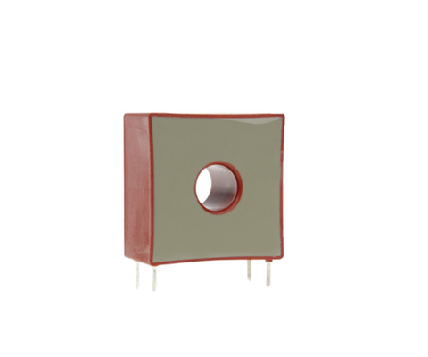
Measuring Transducer (PIN-Version) Description The increasing development and widespread use of electronic devices with higher operating frequencies require current transformers with an extended frequency range. This requirement can be met with specially selected materials in conjunction with an optimized design. Advantages (Electrical) electrical PIN connection according to UL 94 V-0 Current transformer for more accurate current measurement higher accuracy classes 1; 0.5; 0.2 than with standard IE Measurement in the frequency range 16 2/3 to 50kHz Pulse measurement (e.g. 8/20μs) low phase error for power measurement very low remagnetization losses and eddy current losses Nanocrystalline toroidal cores with strip thickness of e.g. 20μm electrically isolated primary and secondary circuits Easy-to-install designs versatile housing options with different through-holes Advantages (Mechanical) easy-to-install designs versatile housing options with different through-holes Typical Applications Industry, Renewable Energies, Railway Technology, Measurement and Testing Technology, Energy, Automation and Building Technology Technical Data Type 1 3 5 10 25 50 Primary current [A] IPN 1 3 5 10 25 50 Max. primary current [A] ImaxPN 1,2 3,6 6 12 30 60 Secondary current [mA] IaN 20 20 20 20 25 50 Power [VA] Psek 0,05 0,05 0,05 0,05 0,063 0,25 Transformation ratio KN 50 150 250 500 1000 1000 Burden resistance [Ω] RB 125 125 125 125 100 100 Burden voltage [V] URB 2,5 2,5 2,5 2,5 2,5 5 Measurement accuracy 50 Hz [%] FU ≤1 ≤1 ≤1 ≤1 ≤1 ≤1 Ambient temperature [°C] TA -25 to +70 -25 to +70 -25 to +70 -25 to +70 -25 to +70 -25 to +70 Frequency range [Hz] f 0.05 to 50 0.05 to 50 0.05 to 50 0.05 to 50 0.05 to 50 0.05 to 50 Insulation test voltage Primary/Secondary / 2 sec [kVac] VP 3 3 3 3 3 3 PIN connection 3-4 / 2-1 3-4 / 2-1 3-4 / 2-1 3-4 / 2-1 NC / 2-1 NC / 2-1 Weight [kg] 0,05 0,05 0,05 0,05 0,05 0,07 Standards EN/IEC 61869-1/2 Dimensions in mm Type Connection [mm²] h [mm] b [mm] t [mm] DL [mm] s [mm] l [mm] a [mm] c [mm] IN/1 3-4 / 2-1 34 33 18 9 1,0 3,5 27,5 10 IN/3 3-4 / 2-1 34 33 18 9 1,0 3,5 27,5 10 IN/5 3-4 / 2-1 34 33 18 9 1,0 3,5 27,5 10 IN/10 3-4 / 2-1 34 33 18 9 1,0 3,5 27,5 10 IN/25 NC / 2-1 34 33 18 9 1,0 3,5 27,5 10 IN/50 NC / 2-1 38 38 20 13 1,0 6,5 30 10 Datasheet All data and configurations can be found in our product datasheet. Download Datasheet Certifications