
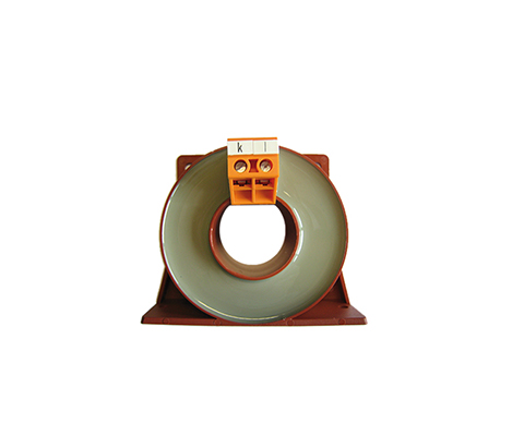
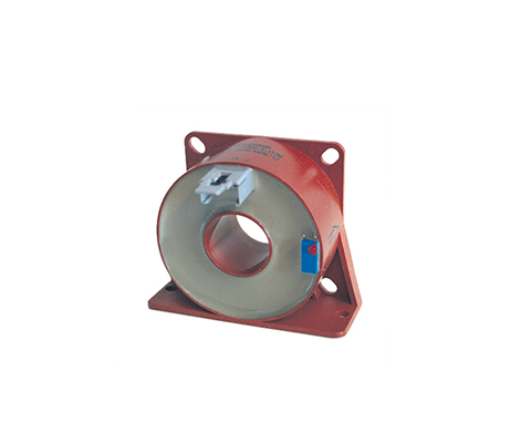
PASSIVE CURRENT TRANSFORMER Series IN (Stranded Wire / Terminal)
Current transformer (stranded wire/terminal) Description The increasing development and distribution of electronic devices with higher working frequencies requires current transformers with an extended frequency range. This requirement can be met with specially selected materials in conjunction with an optimized design. Benefits Stranded wires or terminals according to UL 94 V-0 Current transformer for more accurate current measurement higher accuracy classes 1; 0.5; 0.2 than with standard-IE Measurement in the frequency range 16 2/3 to 50kHz Pulse measurement (e.g. 8/20μs) low phase error for power measurement very low remagnetization losses and eddy current losses Nanocrystalline toroidal cores with a strip thickness of e.g. 20μm electrically isolated primary and secondary circuits easy-to-install designs versatile housing range with different push-through openings Technical data According to: EN/IEC 61869-1/2 Rated primary current: 50 – 1000 A Frequency range: 50 – 50,000 Hz Type 50 100 300 500 1000 Primary current [A] IPN 50 100 300 500 1000 Max. Primary current [A] ImaxPN 60 120 360 600 1200 Secondary current [mA] IaN 1000 1000 1000 1000 1000 Power [VA] Psek 0,5 1,0 2,5 5,0 15 Transformation ratio KN 50 100 300 500 1000 Burden resistance [Ω] RB 0,5 1,0 2,5 5,0 15 Burden voltage [V] URB 0,5 1,0 2,5 5,0 15 Measuring accuracy 50 Hz [%] FU 1,0 1,0 1,0 1,0 1,0 Ambient temperature [°C] TA -25 to +70 -25 to +70 -25 to +70 -25 to +70 -25 to +70 Frequency range [Hz] f 0.05 to 50 0.05 to 50 0.05 to 50 0.05 to 50 0.05 to 50 Insulation test voltage [kVac] VP 3 3 3 3 3 Dimensions in MM Type Connection[mm²] h[mm] b1/b2[mm] t[mm] DL[mm] p/s[mm] a[mm] c1/c2[mm] f[mm] e[mm] l[mm] IE/50 2,5 70 70/89 33 31 57/57 77 15,5/… 4,3 6×4,3 25 IE/100 2,5 70 70/89 33 31 57/57 77 15,5/… 4,3 6×4,3 25 IE/300 2,5 95 94/110 44 40 78/78 100 18/… 5,3 8×5,3 25 IE/500 2,5 95 94/110 44 40 78/78 100 18/… 5,3 8×5,3 25 IE/1000 2,5 141 138/170 55 64 120/120 150 18/25 6,5 10×6,5 25 Data sheet All data and configurations can be found in our product data sheet. Download data sheet
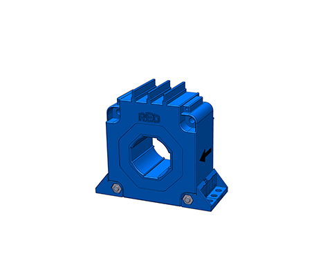
PASSIVE CURRENT TRANSFORMER SERIES IE MODULAR
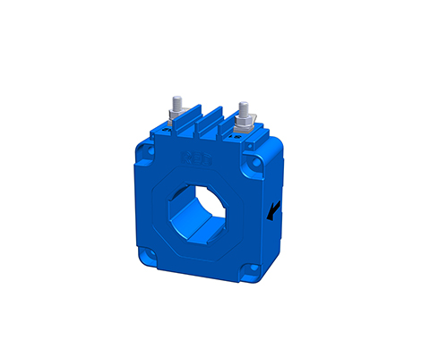
Through-hole current transformer (module base) Description With through-hole current transformers, the primary conductor provided by the customer is inserted through the current transformer opening in the housing. The through-hole opening is oriented to the primary current strength. Wound current transformers have a primary winding and a secondary winding. Both windings are applied to the closed ring core and separated from each other by insulation. This principle is predominantly used for small primary currents. Benefits Bolt or flat plug connection Through-hole current transformer for direct conductor routing Toroidal cores made of high-quality magnetic cores Frequency range 16 2/3 to 400 Hz optional High core output power and high-quality insulation Electrically isolated primary and secondary circuits Easy-to-install module housings Variable connections, e.g., bolts, plugs, flat plugs, strands Versatile housing options with different through-hole openings Typical applications Industry, Renewable Energies, Railway Technology, Energy, Automation and Building Technology Technical data Type IE modular 500 1000 2500 IPN Rated primary current 500 1000 2500 [A] ImaxPN Max. rated primary current 600 1200 3000 [A] IaN Secondary current 1000 [mA] RB Burden resistance 5 15 30 [Ω] URB Burden voltage 5 15 30 [V] PSek Power 5 15 30 [VA] KN Transformation ratio 500 1000 2500 Fi Measurement accuracy (50 Hz) 0,5 0,5 0,5 [%] f Frequency 50-400 [Hz] TA Ambient temperature -25 to +70 [°C] Vp Insulation test 3 [KVac] Connection MS-bolt / flat plug 6.3 x 0.8 [mm²] Weight 0.8 0.8 1.8 [kg] Standards 61869-2 Dimensions in MM Type I [mm] h1/h2 [mm] t1/t2 [mm] s1/s2 [mm] b1/b2 [mm] D [mm] D1xD2 [mm] f [mm] e [mm] x1/x2 [mm] IE modular 500 70 76/35 38/64 57/57 57/50 30,2 30.4×10.4 4,3 4,3 36/15 IE modular 1000 94 100/47 42/72 78/78 78/60 38,5 40.5×13.5 5,3 5,3 36/15 IE modular 2500 135 141/67,5 52/88 102/102 102/70 57,5 60.5×20.5 6,5 6,5 36/15 Data sheet All data and configurations can be found in our product data sheet. Download data sheet
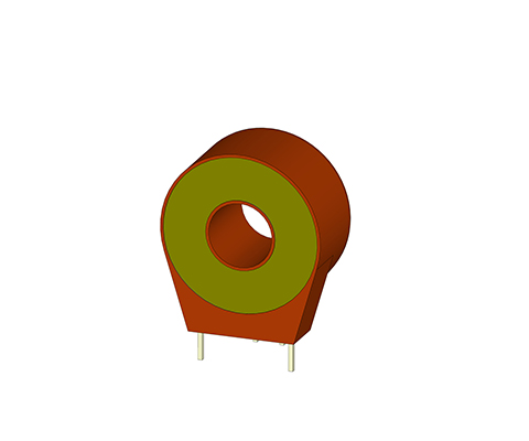
PASSIVE CURRENT TRANSFORMER SERIES IE Pin Version
Through-hole current transformers (PIN version) Description With through-hole current transformers, the primary conductor on the construction side is inserted through the current transformer opening in the housing. The through-hole opening is oriented to the primary current strength. Wound current transformers have a primary winding and a secondary winding. Both windings are applied to the closed ring core and separated from each other by insulation. This principle is predominantly used for small primary currents. Benefits PIN – Connection according to UL 94 V0 Through-hole current transformers for direct conductor routing Design as wound transformer for small currents Ring band cores made of high-quality silicon iron Measurement in the lower frequency range 16 2/3 to 400Hz High core output power and high-quality insulation Electrically isolated primary and secondary circuits Assembly-friendly designs Variable connections e.g. terminals, plugs, flat plugs, stranded wires or PCB mounting Versatile housing options with different through-hole openings Technical Data According to: EN/IEC 61869-1/2 Rated primary current: 1 – 50 A Frequency range: 50 – 400 Hz Rated primary current: 1 – 50 A Type 1 3 5 10 25 50 2 windings through-hole transformer Primary current [A] IPN 1 3 5 10 25 50 Max. primary current [A] ImaxPN 1,2 3,6 6 12 30 60 Secondary current [mA] IaN 20 20 20 20 200 200 Power [VA] Psec 0,1 0,1 0,1 0,1 0,12 0,5 Transformation ratio KN 50 150 250 500 1000 1000 Burden resistance [Ω] RB 250 250 250 250 200 200 Burden voltage [V] URB 5 5 5 5 5 10 Measurement accuracy 50 Hz [%] FU ≤ 1 ≤ 1 ≤ 1 ≤ 1 ≤ 1 ≤ 1 Ambient temperature [°C] TA -25 to + 70 -25 to + 70 -25 to + 70 -25 to + 70 -25 to + 70 -25 to + 70 Frequency range [Hz] f 50 – 400 50 – 400 50 – 400 50 – 400 50 – 400 50 – 400 Insulation test voltage [kVac] VP 3 3 3 3 3 3 Connection [mm²] 3-4/2-1 3-4/2-1 3-4/2-1 3-4/2-1 NC/2-1 NC/2-1 Weight [kg] 0,05 0,05 0,05 0,05 0,05 0,07 Standards EN/IEC 61869-1/2 Dimensions in MM Type PIN connection [A] h [mm] b [mm] t [mm] DL [mm] s [mm] l [mm] a [mm] c [mm] IE/1 3-4/2-1 34 33 18 9 1,0 3,5 27,5 10 IE/3 3-4/2-1 34 33 18 9 1,0 3,5 27,5 10 IE/5 3-4/2-1 34 33 18 9 1,0 3,5 27,5 10 IE/10 3-4/2-1 34 33 18 9 1,0 3,5 27,5 10 IE/25 NC/2-1 34 33 18 9 1,0 3,5 27,5 10 IE/50 NC/2-1 38 38 20 13 1,0 6,5 30 10
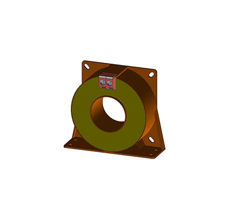
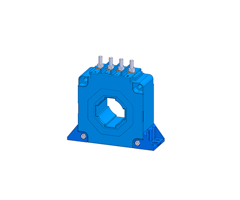
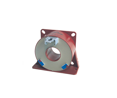
PASSIVE CURRENT TRANSFORMER SERIES IE (Stranded Wire / Terminal)
Feed-through current transformer (stranded wire/terminal) Description With feed-through current transformers, the primary conductor on the construction side is pushed through the current transformer opening in the housing. The feed-through opening is oriented towards the primary current strength. Wound current transformers have a primary winding and a secondary winding. Both windings are applied to the closed toroidal core and separated from each other by insulation. This principle is mainly used for small primary currents. Benefits Stranded wires or terminals according to UL 94 V0 Clip-on current transformer for direct conductor routing Design as a wound transformer for small currents Toroidal cores made of high-quality silicon iron Measurement in the lower frequency range 16 2/3 to 400Hz high core output and high-quality insulation electrically isolated primary and secondary circuits easy-to-install designs versatile housing range with different feed-through openings Advantages (mechanical) easy-to-install designs variable connections e.g. terminals, plugs, flat plugs, stranded wires or PCB mounting versatile housing range with different Feed-through openings very long service life Typical applications Industry, renewable energies, railway technology, energy, automation and building technology Technical data Type 50 100 300 500 1000 2000 3000 Primary current [A] IPN 50 100 300 500 1000 2000 3000 Max. primary current [A] ImaxPN 60 120 360 600 1200 2400 3600 Secondary current [mA] IaN 1000 1000 1000 1000 1000 1000 1000 Power [VA] Psek 0,5 1,0 2,5 10 15 25 25 Translation ratio KN 50 100 300 500 1000 2000 3000 Burden resistance [Ω] RB 0,5 1,0 2,5 10 15 25 25 Burden voltage [V] URB 0,5 1,0 2,5 10 15 25 25 Measuring accuracy 50 Hz [%] FU 1,0 1,0 1,0 1,0 1,0 1,0 1,0 Ambient temperature [°C] TA -25 to + 70 -25 to + 70 -25 to + 70 -25 to + 70 -25 to + 70 -25 to + 70 -25 to + 70 Frequency range [Hz] f 50 to 400 50 to 400 50 to 400 50 to 400 50 to 400 50 to 400 50 to 400 Insulation test voltage [kVac] VP 3 3 3 3 3 3 3 Data sheet You can find all data and configurations in our product data sheet. Download data sheet Certifications
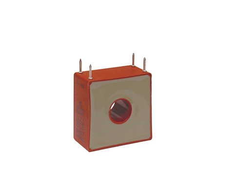
PASSIVE CURRENT TRANSFORMER SERIES IB
Current transformers for PCB mounting Description REO current transformers of the IB series are particularly well suited for mounting on printed circuit boards in the electronics sector of modern drive technology for control purposes and measured value acquisition. Benefits small space requirement PCB mounting according to UL 94 V0 Accuracy class 1 Measurement in the frequency range 50-400Hz low phase error for power measurement very low magnetic reversal and eddy current losses electrically isolated primary and secondary circuits easy-to-install designs Technical data Type IB 0,5/5 IB 0,5/20 IB 0,5/40 Primary current [A] IPN 0 – 5 0 – 20 0 – 40 Max. primary current [A] ImaxPN 7 25 50 Secondary current [mA] IaN 0 – 10 0 – 25 0 – 40 Power [VA] Psek 0 – 0,010 0 – 0,025 0 – 0,040 Translation ratio KN 1:500 1:800 1:1000 Burden resistance [Ω] RB 100 40 25 Burden voltage [V] URB 0 – 1 Measuring accuracy 50 Hz [%] FU ≤ 1 Ambient temperature [°C] TA 0..+85 Frequency range [Hz] f 50 – 400 Insulation test voltage [kVac] VP 3 Dimensions in MM Type Primary current [A] Height [mm] Width [mm] Depth [mm] Opening [mm] PIN thickness [mm] PIN length [mm] IB 05/5 0 – 5 30 26,5/17,5 14,5 10,5 0,7×0,7 5,0 IB 05/20 0 – 20 30 26,5/17,5 14,5 10,5 0,7×0,7 5,0 IB 05/40 0 – 40 30 26,5/17,5 14,5 10,5 0,7×0,7 5,0 Data sheet All data and configurations can be found in our product data sheet. Download data sheet Certifications
ACTIVE CURRENT TRANSFORMER SERIES WKO-2C-B
Dual-core compensation current transformer for railway technology Description The WKO-2C-B current transformer with dual-core technology and Hall effect has an extended frequency response up to 150 kHz and a precise phase response.The WKO-2C-B guarantees improved measuring accuracy of 0.3% in the entire frequency range: DC up to 150 kHz. The completely revised electronics ensure that the C/L current transformer has better drift compensation and an extended temperature range of -40°C to 85°C is achieved. Modular design The current transformer has a modular design and enables a variety of mounting options. The cost-effective basic model consists of a housing with screw connections, lead-through for cables and holes for mounting. Optionally, the converter can be supplied with a mounting kit for busbars, Molex connectors and with feet for horizontal or vertical mounting. According to: EN 50178:1997 UL 94-V0 EN 50178 EN 50155:2007 IEC 61373:2010 Benefits meets the safety standards required in railway technology: EN 50178, EN 50155:2007 and IEC 61373:2010 Shock and vibration testing according to IEC 61373:2010 high current measurement accuracy of 0.3% modular design offers universal mounting options lower sensitivity to external magnetic fields bidirectional and isolated current measurement Current output REO dual-core technology Manufactured with UL-listed materials Technical data Accuracy: better than 0.3% Ambient temperature: -40°C … +85°C Storage temperature: -40°C … +90°C Primary nominal current: 300 – 2000 A Measuring range: 0…4000 A Frequency range: DC – 150 kHz Type Primary RMS nominal current IPN [A] Measuring range IP [A] Supply UC [V] Measuring accuracy XG@Ipn [-20…70°C] of IPN [%] Translation [KN] Secondary RMS nominal current ISN [mA] Secondary winding resistance RS@85°C[Ω] Open circuit current [mA] WKO-2C-B-300 300 0…±2000 ±11.4…25.2 < ± 0.3 2000 150 13 26+IS WKO-2C-B-500 500 0…±1000 ±11.4…25.2 < ± 0.3 5000 100 76 26+IS WKO-2C-B-1000 1000 0…±2700 ±14.25…25.2 < ± 0.3 5000 200 42 26+IS WKO-2C-B-2000 2000 0…±4000 ±14.25…25.2 < ± 0.3 5000 400 26 26+IS Accuracy and dynamic data Type Linearity error e [%] Offset error@25°C Io [mA] Offset drift -25°C…+70°C IOT [mA] Response time tra[μs] Response time 10%-90% ta [μs] dl/dt [A/μs] Bandwidth -1 dB [kHz] WKO-2C-B-300 < ±0.1 ±0.5 < 25 0,2 0,4 400 150 WKO-2C-B-500 < ±0.1 ±0.5 < 25 0,2 0,4 400 150 WKO-2C-B-1000 < ±0.1 ±0.5 < 25 0,2 0,4 400 150 WKO-2C-B-2000 < ±0.1 ±0.5 < 25 0,2 0,4 1000 150 Insulation data Type Creepage distance dCp [mm] Clearance dCi [mm] Tracking resistance [CTI] AC isolation test 50/60 Hz 1min Ud [kV] Impulse voltage test 1.2/50μs Ui [kV] Mass [kg] WKO-2C-B-300 14 13 600 6 12,5 0,340 WKO-2C-B-500 14 13 600 6 12,5 0,260 WKO-2C-B-1000 20 18 600 6 12,5 0,700 WKO-2C-B-2000 35 30 600 6 12,5 1,600 Dimensions in MM Type b1 [mm] b2 [mm] t [mm] s [mm] h [mm] D Ø [mm] D1/D2 [mm] Ø f[mm] Ø e[mm] WKO-2C-B-300 57 70 38 57 70 30,2 10,4/30,4 4,3 4,3 WKO-2C-B-500 57 70 38 57 70 30,2 10,4/30,4 4,3 4,3 WKO-2C-B-1000 78 94 42 78 94 38,5 13,5/40,5 5,3 5,3 WKO-2C-B-2000 102 135 52 102 135 57,5 20,5/60,5 6,5 6,5 Datasheet All data and configurations can be found in our product data sheet. Download datasheet Certifications
Railroad Transformer NTT 400
Auxiliary power transformer Description The REO on-board power supply transformer NTT 400 is designed for on-board power supply systems that are fed by the on-board power converter (BNU). It is used to adapt the voltage and for galvanic isolation of the pulse-width modulated DC link voltage and the consumers of the on-board power supply. A corresponding sine filter must be connected between the transformer and the inverter. The secondary-side load of the isolation transformer can be switching devices, rotating machines, resistive loads, and semiconductor power converter devices. The Transformers are designed for use in vehicles in AC or DC networks (in inverter mode) in the container. This ensures that Transformers from REO are optimally aligned to your application. The main focus of our development is on maximum service life, cost/benefit optimization and safety. Customer-specific complete solutions Auxiliary power transformers can be designed to customer specifications. Are you interested in this product? Please contact us! In addition to standardized components for use in converters, REO offers customer-specific products – as a single component or as a complete solution in a container. The benchmark in railway technology is the availability and safety of passengers. Here, REO offers special solutions that are developed step by step in close cooperation with the customer. Benefits Vibration and shock tested according to DIN 61373 Cat 1 Class B High efficiency Low no-load losses Reduced stray field Low noise Weight-optimized High mechanical strength Installation in the exhaust duct of the power converter, Integration into an existing cooling system Pollution degree PD3 Shield winding possible Alternative switching groups Temperature monitoring Technical data Power: 1-30kVA Nominal voltage:Primary: Nominal voltage: (Normal operation): 3×440 Veff 60 Hz Nominal voltage: (External supply): 3×400 Veff 50 Hz Nominal voltage: (reduced operation): 3×345 Veff 47 Hz Secondary: Voltage: 3×230 Veff Operating temp.: -25°C … +55°C (optional +75°C) Cooling: AN / AF Protection class: IP00 Pollution degree: PD3 Insulation class: F/H Test voltage: EN 50124 / EN 60310 Vibration resistance: Cat.1 Class A/B according to EN61373 Voltages: 24 / 42 / 110 / 230 / 400 / 690 Volt (Optional) Switching group: Optional Type Power[kVA] Total weight[kg] Copper weight[kg] Efficiency[%] UK[%]* NTT 400/1.0 1.0 12 4 92.6 6.7 NTT 400/1.5 1.5 17 5 93.9 5.4 NTT 400/2.5 2.5 26 7 95.0 4.5 NTT 400/4.5 4.5 39 13 95.5 4.1 NTT 400/7.5 7.5 59 22 96.1 3.8 NTT 400/10.0 10.0 73 25 96.4 3.4 NTT 400/15.0 15.0 96 29 97.1 2.6 NTT 400/20.0 20.0 126 36 97.4 2.3 NTT 400/25.0 25.0 150 51 97.5 2.5 NTT 400/30.0 30.0 175 57 97.8 2.1 Dimensions in mm Type L [mm] B [mm] H [mm] N1[mm] N2 [mm] D [mm] NTT 400/1.0 230 93 198 74 176 9 NTT 400/1.5 230 117 198 98 176 9 NTT 400/2.5 265 135 228 105 200 10 NTT 400/4.5 300 151 260 123 224 10 NTT 400/7.5 360 173 305 147 264 10 NTT 400/10.0 420 178 360 148 316 13 NTT 400/15.0 420 208 360 178 316 13 NTT 400/20.0 420 238 360 208 316 13 NTT 400/25.0 480 225 410 189 356 13 NTT 400/30.0 480 248 410 212 356 13
Active Current Transformer Series WKO-2C
Double core technology closed-loop current transformers Description REO has developed a new generation of closed-loop (C/L) current transducers which guarantees increased current measurement accuracy better than 0.3% in the whole frequency range: DC to 150 kHz. The new current transducer type WKO-2C is a completely new development utilizing REO’s double-core technology magnetic design. The unit uses the latest Hall effect elements with an extended frequency response of up to 150 kHz and an accurate phase response. Completely redesigned electronics ensure that the new C/L current transducer has better drift compensation and an extended temperature range from -40°C to 85°C. Modular mounting plates providing universal mounting options All REO current transformers in the WKO-2C series work according to the proven compensation principle and are suitable for measuring direct and alternating currents. According to EN 50178:1997, UL 94-V0 EN50121, EN55011 IEC61869-1, IEC61869-8, IEC61010-1 According to: EN 50178:1997, UL 94-V0 Benefits High current measurement accuracy of 0.3% Modular mounting plates providing universal mounting options Lower sensitivity to external magnetic fields Bidirectional and isolated current measurement up to ±750A current output Modular mounting plates REO double core technology All materials manufactured using UL-listed materials Typical applications Power electronics: AC-DC motor control, inverter technology, drive control Railway technology: drive control Renewable energy: control and monitoring of wind turbines Technical data Accuracy: better than 0.3% Ambient temperature: -40 ° C… + 85 ° C Storage temperature: -40 ° C… + 90 ° C Primary rated current: 300 – 2000 A Measurement range: 0… 4000 A Frequency range: 150000 Hz Type Primary RMS NominalcurrentIPN [A] Measurement rangeIP[A] Feed-inUC [V] Measurement accuracyXG@Ipn[-20…70°C]von IPN [%] RatioKN Secondary RMSNominal currentISN [mA] Secondary windingResistorRs@85°C [Ω] No-load current[mA] WKO-2C-300 300 0…±2000 ±11,4…25,2 >±0,3 2000 150 13 26+IS WKO-2C-500 500 0…±1000 ±11,4…25,2 >±0,3 5000 100 76 26+IS WKO-2C-1000 1000 0…±2700 ±14,25…25,2 >±0,3 5000 200 42 26+IS WKO-2C-2000 2000 0…±4000 ±14,25…25,2 >±0,3 5000 400 26 26+IS ACCURACY AND DYNAMIC DATA Type Linearity error e [%] Offset error@25°C IO [mA] Offset Drift -25°C…+70°C IOT [mA] Response time tRA [μs] Response time10%-90%ta [μs] dl/dt ta [A/μs] Bandwidth -1 dB [kHz] WKO-2C-300 < ±0,1 ±0,5 <25 0,2 0,4 400 150 WKO-2C-500 < ±0,1 ±0,5 <25 0,2 0,4 400 150 WKO-2C-1000 < ±0,1 ±0,5 <25 0,2 0,4 400 150 WKO-2C-2000 < ±0,1 ±0,5 <25 0,2 0,4 1000 150 ISOLATION DATA Type Creepage distance dCp [mm] Air gap dCi [mm] tracking resistance [CTI] AC insulation test 50/60Hz 1min Ud [kV] Pulse voltage test 1.2/50μs Ui [kV] Mass [kg] WKO-2C-300 14 13 600 6 12,5 0,340 WKO-2C-500 14 13 600 6 12,5 0,260 WKO-2C-1000 20 18 600 6 12,5 0,700 WKO-2C-2000 35 30 600 6 12,5 1,600 Mechanical data Type b1[mm] b2[mm] t[mm] s[mm] h[mm] D Ø[mm] D1/D2[mm] Ø f[mm] Ø e[mm] WKO-2C-300 57 70 38 57 70 30,2 10,4/30,4 4,3 4,3 WKO-2C-500 57 70 38 57 70 30,2 10,4/30,4 4,3 4,3 WKO-2C-1000 78 94 42 78 94 38,5 13,5/40,5 5,3 5,3 WKO-2C-2000 102 135 52 102 135 57,5 20,5/60,5 6,5 6,5 Data sheet All data and configurations can be found in our product data sheet. Download data sheet Certifications
Active Current Transformer Series WKO
Closed-loop current transformers Description Closed-loop current transformers The WKO current sensors work according to the proven compensation principle and are suitable for measuring direct, alternating and mixed currents. The primary current flow generates a magnetic flux, which is compensated by an internal secondary coil.The current evaluation is realized with an electronic circuit and a Hall sensor. The secondary compensation current is an exact reflection of the primary current to be measured. Unique Selling Point Measurement of direct, alternating and mixed currents Very high precision and short response time Broad frequency spectrum and low-temperature drift Very good linearity and overcurrent resistance No additional losses in the measuring circuit (DC to 150 kHz) Current output for lengthy transmission lines High-quality UL-listed insulating materials (e.g. UL94-V0) UNIQUE SELLING POINT Robust housing designs (for horizontal/vertical mounting) Variable connections, e.g. clamps, plugs, flat-cable plugs or cables Wide range of housings with various push-through openings Push-through openings Typical applications Industry, Renewable energy sources, Railway engineering, Energy, automation and building technology ELECTRICAL DATA Type WKO 25 WKO 50 WKO 100 WKO 300 WKO 500 WKO 1000 Primary RMS nominal current IPN [A] 25 50 100 300 500 1000 Measuring range IP [A] 0…±35 0…±70 0…±150 0…±500 0…±1000 0…±1500 Supply UC [V] ±12 …15 ±12 …15 ±12 …15 ±12 …15 ±12 …24 ±12 …24 Measuring accuracy XG@Ipn [-20…70°C] from IPN [%] > ±0,9 > ±1 > ±1 > ±1 > ±1 > ±1 Translation KN 1000 1000 1000 2000 5000 5000 Secondary RMS Nominal current ISN [mA] 25 50 100 150 100 200 Secondary winding Resistive sand RS@70°C [Ω] 16 43 24 30 72 48 Idle current [mA] 36+IS 11+IS 36+IS 36+IS 36+IS 24+IS ACCURACY AND DYNAMIC DATA Type WKO 25 WKO 50 WKO 100 WKO 300 WKO 500 WKO 1000 Linearity error e [%] < ±0,1 < ±0,1 < ±0,1 < ±0,1 < ±0,1 < ±0,1 Offset error@25°CIO [mA] > 0,3 > 0,3 > 0,4 > 0,2 > 0,2 > 0,3 Offset Drift-25°C…+70°CIOT [mA] > 0,5 > 0,5 > 1 > 0,5 > 0,5 > 0,5 Response time tra[μs] > 0,5 > 0,5 > 0,5 > 0,5 > 0,5 > 0,5 Response time 10%-90% ta [μs] > 1 > 1 > 1 > 1 > 1 > 1 dl/dt ta [A/μs] > 50 > 50 > 100 > 100 > 100 > 100 Bandwidth -1 dB [kHz] DC…150 DC…200 DC…100 DC…100 DC…100 DC…100 ISOLATION DATA Type WKO 25 WKO 50 WKO 100 WKO 300 WKO 500 WKO 1000 Creepage distance dCp [mm] 4 8 10 10 10 15 Air section dCi[mm] 3 7 9 9 9 12 Leakage current resistance [CTI] 600 600 600 600 600 600 AC insulation test 50/60Hz 1min Ud [kV] 3,8 3,8 3,8 3,8 6 6 Pulse voltage test 1,2/50μs Ui[kV] 6 6 6 6 12,5 14,5 Mass [kg] 0,08 0,022 0,125 0,125 0,240 0,450 Dimensions in MM Type Pin connection/ 4-pin h [mm] b [mm] b1/b2 [mm] t [mm] DL [mm] p/s [mm] a/a1 [mm] c1/c2 [mm] f [mm] e [mm] l [mm] WKO 25 A; -U; +U 39 39 – 26 10 – 2 x 10/6,5 25/6,5 M3 6,0 x 4,0 9 WKO 50 A; -U; +U Please find in the drawing WKO 100 A; -U; +U 55 – 55/68 26 20,2 45/45 – 13,0/– 4,3 6,0×4,0 12 WKO 300 A; -U; +U 55 – 55/68 26 20,2 45/45 – 13,0/– 4,3 6,0×4,0 12 WKO 500 A; -U; +U 70 – 70/89 33 31,0 57/57 – 15,2/– 4,3 6,0×4,3 12 WKO 1000 A; -U; +U 95 – 94/110 44 40,0 78/78 – 18,0/– 5,3 8,0×5,3 12 Data sheet All data and configurations can be found in our product data sheet. Download data sheet Certifications
ACTIVE CURRENT TRANSFORMER WDI SERIES
AC/DC Direct-Imaging Current Transformers (Open-Loop Converters) Description Direct-imaging current transformer (Open-Loop Converter) The WDI current sensor is a direct-imaging current transformer designed for measuring DC and AC currents. The primary current flow generates a magnetic flux, which is evaluated in the air gap by means of a magnetic circuit and Hall sensor. An electronic circuit processes the signal from the Hall sensor and outputs an exact image of the primary current with a voltage at the output. Advantages (Electrical) Measurement of DC and AC currents Voltage output low power consumption no additional losses in the measuring circuit high-quality insulation materials listed according to UL safe, electrically isolated primary and secondary circuits good value for money Advantages (Mechanical) low weight robust housing designs (horizontal/vertical mounting) Connections: terminals, plugs, flat connectors or cables versatile range of housings with different push-through openings Typical applications Industry, renewable energies, railway technology, energy, automation and building technology Technical data Type 25 150 300 Primary current [A] ÎPN Peak 25 150 300 Max. Primary current [A] ÎmaxPN Peak 0- ± 30 0- ± 180 0- ± 360 Secondary current [mA] ÎoutPN ± 5 ± 5 ± 5 Min. load resistance RBmin ± 15 Vdc ± 30A peak=2 ± 150 peak=2 ± 300 peak=2 ± 180A peak=2 ± 360A peak=2 Max. load resistance RBmax ± 15 Vdc ± 30A peak=10 ± 150 peak=2 ± 300 peak=2 ± 180A peak=2 ± 360A peak=2 Max. peak output voltage [V] ÜaN Peak ± 10 ± 10 ± 10 Operating voltage [Vdc] US ± 5% ± 15 ± 15 ± 15 No-load current [mA] IBO (@ ± 15 V) + loutpN 9 9 9 Insulation test voltage [kV] VP r.m.s. 50 Hz 3 3 3 Impulse withstand voltage[kV] VW 1,2/50μs 3 5 5 Measuring accuracy 50 Hz [%] FU @IPN, TA=25°C ± 0.6 ± 0.6 ± 0.6 Linearity error [%] FLU @TA=25°C ≤ 1.0 ≤ 1.0 ≤ 1.0 Offset voltage [mV] Uo @IPN = 0, TA = 25°C 20 20 20 Drift offset voltage [mV] △Uo Io -25°C…+70°C 60 60 60 Temperature drift [%K] %/△T ≤ 0.05 ≤ 0.05 ≤ 0.05 Response time [μs] tr @ 90% of IPN 25 25 25 Frequency range [kHz] f (-3 dB) DC … 10 (-3 dB) DC … 10 (-3 dB) DC … 10 Ambient temperature [°C] TA -25 to + 75 -25 to + 75 -25 to + 75 Storage temperature[°C] Ts -10 to + 85 -10 to + 85 -10 to + 85 Weight [kg] m 0,075 0,075 0,075 Creepage distance [mm] dCp 4 10 10 Clearance [mm] dCpi 3 9 9 DIMENSIONS IN MM Type PIN connection / 4-pin h [mm] b [mm] b1/b2 [mm] t [mm] DL [mm] p/s [mm] a/a1 [mm] c1/c2 [mm] f [mm] e [mm] l [mm] WDI 25 A; O,-U; +U 39 39 – 26,5 10 – 3 x 10/6,5 25/6,5 M4 – 9 WDI 150 A; O,-U; +U 55 – 55/68 26 20,2 45/45 60/– 13/– 4,3 6,0 x 4,0 23 WDI 300 A; O,-U; +U 55 – 55/68 26 20,2 45/45 60/– 13/– 4,3 6,0 x 4,0 23 Data sheet All data and configurations can be found in our product data sheet. Download data sheet Certifications