| Type | Nominal voltage U [V] |
Nominal current I [A] |
Inductance L [mH] |
Losses P [W] |
Mass [kg] |
Mass Cu [kg] |
| N CNW 892 / 8 | 600 50 / 60 Hz |
8 | 9,4 | 30 | 1,4 | 0,6 |
| N CNW 892 / 11 | 600 50 / 60 Hz |
11 | 6,2 | 30 | 2,0 | 0,6 |
| N CNW 892 / 15 | 600 50 / 60 Hz |
15 | 4,8 | 40 | 2,4 | 0,8 |
| N CNW 892 / 20 | 800 50 / 60 Hz |
20 | 3,3 | 30 | 3,0 | 1,2 |
| N CNW 892 / 28 | 800 50 / 60 Hz |
28 | 2,4 | 40 | 3,8 | 2,1 |
| N CNW 892 / 34 | 800 50 / 60 Hz |
34 | 2,0 | 40 | 4,0 | 1,3 |
| N CNW 892 / 40 | 800 50 / 60 Hz |
40 | 1,6 | 70 | 5,0 | 1,2 |
| N CNW 892 / 55 | 800 50 / 60 Hz |
55 | 1,2 | 80 | 6,0 | 1,4 |
| N CNW 892 / 70 | 800 50 / 60 Hz |
70 | 0,98 | 80 | 8,0 | 2,3 |
| N CNW 892 / 85 | 800 50 / 60 Hz |
85 | 0,81 | 90 | 11,0 | 2,0 |
| N CNW 892 / 100 | 800 50 / 60 Hz |
100 | 0,67 | 120 | 13,0 | 1,8 |
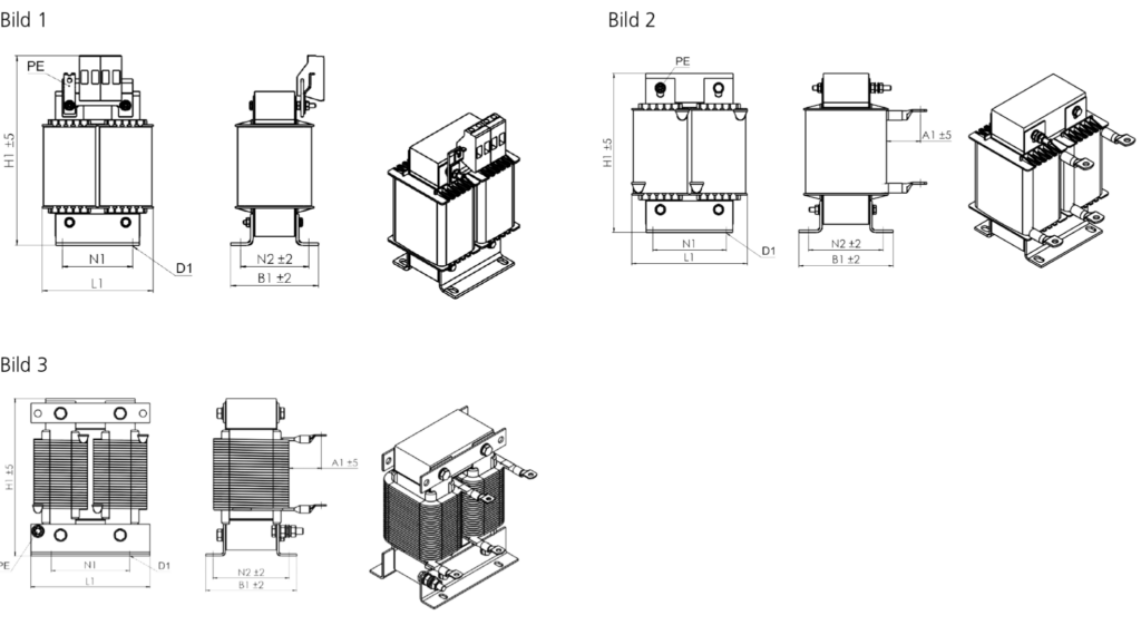
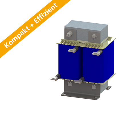
| Type | Dimensions L (mm) | Dimensions B (mm) | Dimensions H (mm) | Mounting N1 (mm) | Mounting N2 (mm) | Mounting D1 (mm) | Terminal connection/ Cable lug [mm²] |
PE connection | Connection A1 (mm) | Image |
| N CNW 892 / 8 | 80 | 53 | 135 | 50 | 39 | 4,8 x 9 | 4,0 | M4 | 1 | |
| N CNW 892 / 11 | 80 | 63 | 135 | 50 | 49 | 4,8 x 9 | 4,0 | M4 | 1 | |
| N CNW 892 / 15 | 100 | 66 | 155 | 63 | 49 | 6 x 10 | 4,0 | M4 | 1 | |
| N CNW 892 / 20 | 100 | 66 | 140 | 63 | 49 | 6 x 10 | 10 (M4) | M4 | 35 | 2 |
| N CNW 892 / 28 | 100 | 81 | 140 | 63 | 64 | 6 x 10 | 10 (M5) | M4 | 35 | 2 |
| N CNW 892 / 34 | 100 | 81 | 140 | 63 | 64 | 6 x 10 | 16 (M5) | M4 | 35 | 2 |
| N CNW 892 / 40 | 120 | 87,5 | 165 | 76 | 68,5 | 7 x 13 | 10 (M6) | M6 | 40 | 3 |
| N CNW 892 / 55 | 120 | 97,5 | 165 | 76 | 78,5 | 7 x 13 | 16 (M6) | M6 | 40 | 3 |
| N CNW 892 / 70 | 152 | 92 | 205 | 100 | 73 | 7 x 13 | 25 (M8) | M8 | 45 | 3 |
| N CNW 892 / 85 | 152 | 112 | 205 | 100 | 93 | 7 x 13 | 25 (M8) | M8 | 45 | 3 |
| N CNW 892 / 100 | 160 | 127 | 215 | 100 | 103 | 7 x 13 | 25 (M8) | M8 | 45 | 3 |
All data and configurations can be found in our product datasheet.