
NTT 500 Leakage Field Transformer
Especially in the railway sector, when it comes to maximum comfort and safety for passengers, space-saving, safe and durable components are required.
PASSIVE CURRENT TRANSFORMER SERIES IN-I
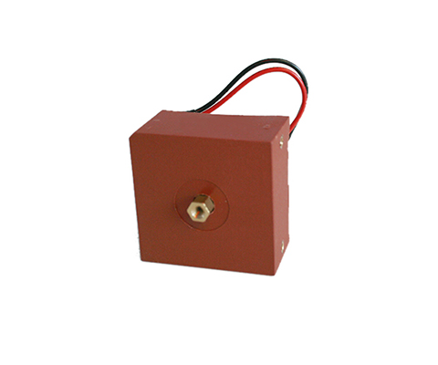
Pulse Current Transformers Description Due to the selected materials, REO pulse current transformers of the IN-I series can represent current with high accuracy and the corresponding transformation ratio – making them particularly suitable for power measurement, current monitoring and analysis, and for use in solar inverters. They are also ideally suited for use in active filters, as they can be designed for measuring current peaks. The primary current is measured via a current conductor that passes through the closed toroidal core. The magnetic field generated by the current flow through the conductor is absorbed by the toroidal core and, according to the transformation ratio of the secondary winding, generates a smaller current for measurement purposes. This method reduces a high measurement current to a significantly smaller current and additionally separates it from the primary circuit by means of safe galvanic isolation. Benefits Very precise current measurement Class 0.2 Pulse current measurement Low-loss core (core losses <10W/kg at 20kHz/200mT) Housing made of UL VO material (Conductor must be positioned) Diverse applications, e.g., for:Active filters, EMC measurements, and pulse current measurements Typical Applications Measurement and Testing Technology Technical Data Type 50 100 200 Primary current [A] IPN r.m.s 0 – 50 0 – 100 0 – 200 Max. primary current [A] ImaxPN r.m.s ± 60 ± 120 ± 240 Secondary current [mA] IaN r.m.s 0 – 50 0 – 100 0 – 200 Power [VA] Psek 0,5 1,0 1,5 Transformation ratio KN 1: 1000 1000 1000 Burden resistance [Ω] RB 200 100 37,5 Burden voltage [V] URB r.m.s 10 10 7,5 Measurement accuracy 50 Hz [%] FU ± 0.2 ± 0.2 ± 0.2 Ambient temperature [°C] TA -20 to +70 -20 to +70 -20 to +70 Frequency [Hz] f 0.050 to 50 0.050 to 50 0.050 to 50 Insulation test voltage Primary / Secondary / 2 sec [kVac] VP r.m.s 50 Hz 3 3 3 Storage temperature TS -25 to +85 -25 to +85 -25 to +85 Coil resistance RS @ TA = 25°C 11,5 11,5 9 Weight m 0,270 0,270 0,270 Standards EN/IEC 61869-1/2 Tracking resistance Housing / Casting resin 550 / 600M Creepage distance dCp 10 10 10 Clearance distance dCI 9 9 9 Datasheet All data and configurations can be found in our product datasheet. Download Datasheet Certifications
PASSIVE CURRENT TRANSFORMER Series IN (Stranded Wire / Terminal)
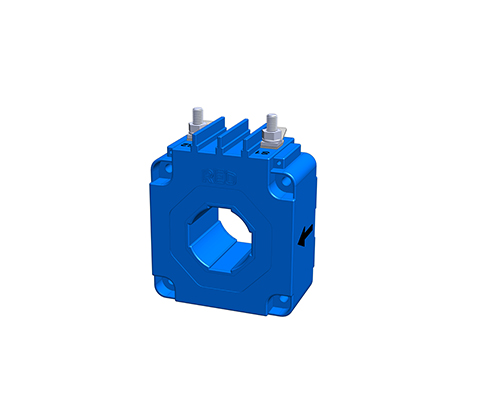
Current transformer (stranded wire/terminal) Description The increasing development and distribution of electronic devices with higher working frequencies requires current transformers with an extended frequency range. This requirement can be met with specially selected materials in conjunction with an optimized design. Benefits Stranded wires or terminals according to UL 94 V-0 Current transformer for more accurate current measurement higher accuracy classes 1; 0.5; 0.2 than with standard-IE Measurement in the frequency range 16 2/3 to 50kHz Pulse measurement (e.g. 8/20μs) low phase error for power measurement very low remagnetization losses and eddy current losses Nanocrystalline toroidal cores with a strip thickness of e.g. 20μm electrically isolated primary and secondary circuits easy-to-install designs versatile housing range with different push-through openings Technical data According to: EN/IEC 61869-1/2 Rated primary current: 50 – 1000 A Frequency range: 50 – 50,000 Hz Type 50 100 300 500 1000 Primary current [A] IPN 50 100 300 500 1000 Max. Primary current [A] ImaxPN 60 120 360 600 1200 Secondary current [mA] IaN 1000 1000 1000 1000 1000 Power [VA] Psek 0,5 1,0 2,5 5,0 15 Transformation ratio KN 50 100 300 500 1000 Burden resistance [Ω] RB 0,5 1,0 2,5 5,0 15 Burden voltage [V] URB 0,5 1,0 2,5 5,0 15 Measuring accuracy 50 Hz [%] FU 1,0 1,0 1,0 1,0 1,0 Ambient temperature [°C] TA -25 to +70 -25 to +70 -25 to +70 -25 to +70 -25 to +70 Frequency range [Hz] f 0.05 to 50 0.05 to 50 0.05 to 50 0.05 to 50 0.05 to 50 Insulation test voltage [kVac] VP 3 3 3 3 3 Dimensions in MM Type Connection[mm²] h[mm] b1/b2[mm] t[mm] DL[mm] p/s[mm] a[mm] c1/c2[mm] f[mm] e[mm] l[mm] IE/50 2,5 70 70/89 33 31 57/57 77 15,5/… 4,3 6×4,3 25 IE/100 2,5 70 70/89 33 31 57/57 77 15,5/… 4,3 6×4,3 25 IE/300 2,5 95 94/110 44 40 78/78 100 18/… 5,3 8×5,3 25 IE/500 2,5 95 94/110 44 40 78/78 100 18/… 5,3 8×5,3 25 IE/1000 2,5 141 138/170 55 64 120/120 150 18/25 6,5 10×6,5 25 Data sheet All data and configurations can be found in our product data sheet. Download data sheet
PASSIVE CURRENT TRANSFORMER SERIES IE MODULAR
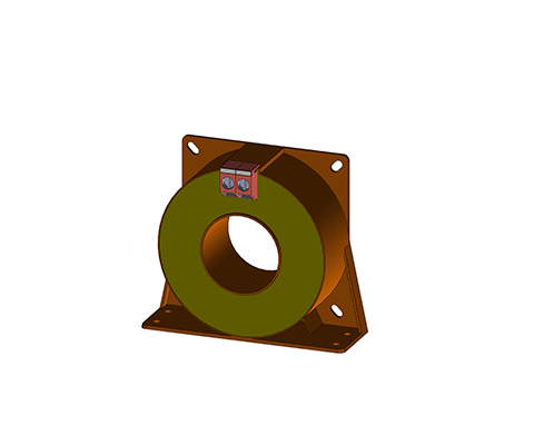
Through-hole current transformer (module base) Description With through-hole current transformers, the primary conductor provided by the customer is inserted through the current transformer opening in the housing. The through-hole opening is oriented to the primary current strength. Wound current transformers have a primary winding and a secondary winding. Both windings are applied to the closed ring core and separated from each other by insulation. This principle is predominantly used for small primary currents. Benefits Bolt or flat plug connection Through-hole current transformer for direct conductor routing Toroidal cores made of high-quality magnetic cores Frequency range 16 2/3 to 400 Hz optional High core output power and high-quality insulation Electrically isolated primary and secondary circuits Easy-to-install module housings Variable connections, e.g., bolts, plugs, flat plugs, strands Versatile housing options with different through-hole openings Typical applications Industry, Renewable Energies, Railway Technology, Energy, Automation and Building Technology Technical data Type IE modular 500 1000 2500 IPN Rated primary current 500 1000 2500 [A] ImaxPN Max. rated primary current 600 1200 3000 [A] IaN Secondary current 1000 [mA] RB Burden resistance 5 15 30 [Ω] URB Burden voltage 5 15 30 [V] PSek Power 5 15 30 [VA] KN Transformation ratio 500 1000 2500 Fi Measurement accuracy (50 Hz) 0,5 0,5 0,5 [%] f Frequency 50-400 [Hz] TA Ambient temperature -25 to +70 [°C] Vp Insulation test 3 [KVac] Connection MS-bolt / flat plug 6.3 x 0.8 [mm²] Weight 0.8 0.8 1.8 [kg] Standards 61869-2 Dimensions in MM Type I [mm] h1/h2 [mm] t1/t2 [mm] s1/s2 [mm] b1/b2 [mm] D [mm] D1xD2 [mm] f [mm] e [mm] x1/x2 [mm] IE modular 500 70 76/35 38/64 57/57 57/50 30,2 30.4×10.4 4,3 4,3 36/15 IE modular 1000 94 100/47 42/72 78/78 78/60 38,5 40.5×13.5 5,3 5,3 36/15 IE modular 2500 135 141/67,5 52/88 102/102 102/70 57,5 60.5×20.5 6,5 6,5 36/15 Data sheet All data and configurations can be found in our product data sheet. Download data sheet
PASSIVE CURRENT TRANSFORMER SERIES IE (Stranded Wire / Terminal)
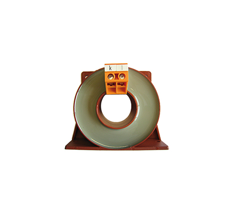
Feed-through current transformer (stranded wire/terminal) Description With feed-through current transformers, the primary conductor on the construction side is pushed through the current transformer opening in the housing. The feed-through opening is oriented towards the primary current strength. Wound current transformers have a primary winding and a secondary winding. Both windings are applied to the closed toroidal core and separated from each other by insulation. This principle is mainly used for small primary currents. Benefits Stranded wires or terminals according to UL 94 V0 Clip-on current transformer for direct conductor routing Design as a wound transformer for small currents Toroidal cores made of high-quality silicon iron Measurement in the lower frequency range 16 2/3 to 400Hz high core output and high-quality insulation electrically isolated primary and secondary circuits easy-to-install designs versatile housing range with different feed-through openings Advantages (mechanical) easy-to-install designs variable connections e.g. terminals, plugs, flat plugs, stranded wires or PCB mounting versatile housing range with different Feed-through openings very long service life Typical applications Industry, renewable energies, railway technology, energy, automation and building technology Technical data Type 50 100 300 500 1000 2000 3000 Primary current [A] IPN 50 100 300 500 1000 2000 3000 Max. primary current [A] ImaxPN 60 120 360 600 1200 2400 3600 Secondary current [mA] IaN 1000 1000 1000 1000 1000 1000 1000 Power [VA] Psek 0,5 1,0 2,5 10 15 25 25 Translation ratio KN 50 100 300 500 1000 2000 3000 Burden resistance [Ω] RB 0,5 1,0 2,5 10 15 25 25 Burden voltage [V] URB 0,5 1,0 2,5 10 15 25 25 Measuring accuracy 50 Hz [%] FU 1,0 1,0 1,0 1,0 1,0 1,0 1,0 Ambient temperature [°C] TA -25 to + 70 -25 to + 70 -25 to + 70 -25 to + 70 -25 to + 70 -25 to + 70 -25 to + 70 Frequency range [Hz] f 50 to 400 50 to 400 50 to 400 50 to 400 50 to 400 50 to 400 50 to 400 Insulation test voltage [kVac] VP 3 3 3 3 3 3 3 Data sheet You can find all data and configurations in our product data sheet. Download data sheet Certifications
Railroad Transformer NTT 400
Auxiliary power transformer Description The REO on-board power supply transformer NTT 400 is designed for on-board power supply systems that are fed by the on-board power converter (BNU). It is used to adapt the voltage and for galvanic isolation of the pulse-width modulated DC link voltage and the consumers of the on-board power supply. A corresponding sine filter must be connected between the transformer and the inverter. The secondary-side load of the isolation transformer can be switching devices, rotating machines, resistive loads, and semiconductor power converter devices. The Transformers are designed for use in vehicles in AC or DC networks (in inverter mode) in the container. This ensures that Transformers from REO are optimally aligned to your application. The main focus of our development is on maximum service life, cost/benefit optimization and safety. Customer-specific complete solutions Auxiliary power transformers can be designed to customer specifications. Are you interested in this product? Please contact us! In addition to standardized components for use in converters, REO offers customer-specific products – as a single component or as a complete solution in a container. The benchmark in railway technology is the availability and safety of passengers. Here, REO offers special solutions that are developed step by step in close cooperation with the customer. Benefits Vibration and shock tested according to DIN 61373 Cat 1 Class B High efficiency Low no-load losses Reduced stray field Low noise Weight-optimized High mechanical strength Installation in the exhaust duct of the power converter, Integration into an existing cooling system Pollution degree PD3 Shield winding possible Alternative switching groups Temperature monitoring Technical data Power: 1-30kVA Nominal voltage:Primary: Nominal voltage: (Normal operation): 3×440 Veff 60 Hz Nominal voltage: (External supply): 3×400 Veff 50 Hz Nominal voltage: (reduced operation): 3×345 Veff 47 Hz Secondary: Voltage: 3×230 Veff Operating temp.: -25°C … +55°C (optional +75°C) Cooling: AN / AF Protection class: IP00 Pollution degree: PD3 Insulation class: F/H Test voltage: EN 50124 / EN 60310 Vibration resistance: Cat.1 Class A/B according to EN61373 Voltages: 24 / 42 / 110 / 230 / 400 / 690 Volt (Optional) Switching group: Optional Type Power[kVA] Total weight[kg] Copper weight[kg] Efficiency[%] UK[%]* NTT 400/1.0 1.0 12 4 92.6 6.7 NTT 400/1.5 1.5 17 5 93.9 5.4 NTT 400/2.5 2.5 26 7 95.0 4.5 NTT 400/4.5 4.5 39 13 95.5 4.1 NTT 400/7.5 7.5 59 22 96.1 3.8 NTT 400/10.0 10.0 73 25 96.4 3.4 NTT 400/15.0 15.0 96 29 97.1 2.6 NTT 400/20.0 20.0 126 36 97.4 2.3 NTT 400/25.0 25.0 150 51 97.5 2.5 NTT 400/30.0 30.0 175 57 97.8 2.1 Dimensions in mm Type L [mm] B [mm] H [mm] N1[mm] N2 [mm] D [mm] NTT 400/1.0 230 93 198 74 176 9 NTT 400/1.5 230 117 198 98 176 9 NTT 400/2.5 265 135 228 105 200 10 NTT 400/4.5 300 151 260 123 224 10 NTT 400/7.5 360 173 305 147 264 10 NTT 400/10.0 420 178 360 148 316 13 NTT 400/15.0 420 208 360 178 316 13 NTT 400/20.0 420 238 360 208 316 13 NTT 400/25.0 480 225 410 189 356 13 NTT 400/30.0 480 248 410 212 356 13
Traction Transformer NTT 400 U
On-board power supply transformer for underground construction Description The REO on-board power supply transformer NTT 400 U is designed for on-board power supply systems that are fed by the on-board power converter (BNU). The NTT 400 U transformer refers to the complete, ready-to-use unit with transformer and housing. The transformer is used to adapt the voltage and for galvanic isolation of the pulse-width modulated intermediate circuit voltage and the consumers of the vehicle electrical system. A corresponding sine filter must be connected between the transformer and the inverter. The secondary-side load of the isolation transformer can be switchgear, rotating machines, ohmic loads and semiconductor power converter devices. The Transformers are designed for use in vehicles in AC or DC networks (in inverter operation) in the container. This ensures that REO Transformers are optimally aligned to your application. The main focus of our development is on maximum service life, cost/benefit optimization and safety. Power: 10-30 kVA Nominal voltage: Primary: Nominal voltage: (Normal operation): 3×440 Vrms 60 Hz Nominal voltage: (External supply): 3×400 Vrms 50 Hz Nominal voltage: (reduced operation): 3×345 Vrms 47 Hz Secondary: Voltage: 3×230 Vrms Operating temp.: -25°C … +55°C (optional +75°C) Humidity: max 95% Pollution degree: PD4 Insulation class: F/H Test voltage: EN 50124 / EN 60310 Vibration resistance: Cat.1 Class A/B according to EN61373 Voltages: 24 / 42 / 110 / 230 / 400 / 690 Volt (Optional) Switching group: Optional Customer-specific complete solutions On-board power supply transformers can be designed to be customer-specific. Are you interested in this product? Please contact us! In addition to standardized components for use in converters, REO offers customer-specific products – as a single component or as a complete solution in a container. The benchmark in railway technology is the availability and safety of passengers. Here, REO offers special solutions that are developed step by step in close cooperation with the customer. Benefits Vibration and shock tested according to DIN 61373 Cat 1 Class B high efficiency low no-load losses reduced stray field low noise emission Weight-optimized high mechanical strengthCooling ON Pollution degree PD4 various power classes Technical data Nominal power : 10000 – 30000 VA Input voltage : 3×440 V Type Power[kVA] Total weight[kg] Copper weight[kg] Efficiency [%] Uk[%]* NTT 400 U/15.0 15.0 96 29 97.1 2.6 NTT 400 U/20.0 20.0 126 36 97.4 2.3 NTT 400 U/25.0 25.0 150 51 97.5 2.5 NTT 400 U/30.0 30.0 175 57 97.8 2.1 Dimensions in mm Type L [mm] B1 [mm] B2 [mm] H [mm] N1 [mm] N2 [mm] D [mm] Mass [kg] NTT 400 U/15.0 510 520 350 345 385 460 10 120 NTT 400 U/20.0 540 520 355 365 410 440 13 147 NTT 400 U/25.0 575 500 355 396 455 440 13 175 NTT 400 U/30.0 561 536 392 351 300 456 13 195
Leakage Field Transformer RUT 500
Leakage Field Transformer Description Especially in the railway sector, where maximum comfort and safety for passengers are paramount, space-saving, safe, and durable components are required. Current dips or voltage losses can cause various undesirable effects, such as loss of motor power. The REO leakage field transformer ensures a harmonious progression of currents and voltages at the output, thus filtering harmonics and limiting ripple current. Due to the spatial separation of primary and secondary windings and the associated targeted increase of the magnetic leakage flux, the REO leakage field transformer achieves loose magnetic coupling. This combines the function of a transformer (voltage transformation and galvanic isolation) and a sine filter choke. Selection options Various power classes: 50 kVA, 100 kVA, 150 kVA, and 200 kVA Voltage drop uk 10%, 20%, and 30% Voltage ratio / windings freely selectable Winding freely selectable according to material and insulation class, and optimized for low eddy current loss Benefits Space-saving (transformer and Drossel in one component) Longer motor life by limiting current peaks Cost-effective Optimized for railway operation (high degree of contamination, shock and vibration tested, salt spray and immersion bath tested) Technical Data Rated power: 71000 – 275000 VA Input voltage: 210 – 1660 V
Phase-angle Control REOVIB SMART SYSTEM
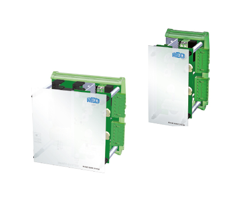
IP00, for DIN rail mounting Description REOVIB SMART SYSTEM BASE MODULE Open design for DIN rail mounting with one output channel of max. 6 A with level control/jamming circuit. The base module provides power for expansion modules. This allows additional output modules to be connected up to a total current of 10 A. REOVIB SMART SYSTEM EXPANSION MODULE Open design for DIN rail mounting. The expansion module has one output channel max. 6 A with level control/jamming circuit and can be set up together with the base module and several expansion modules. REOVIB SMART SINGLE Open design for DIN rail mounting with one output channel of max. 6 A. Benefits cost-effective Phase-Angle Controls with essential functions Can be used as a single device or modular version for multiple outputs Output current up to 6 A DIN rail mounting Versions with level control/jamming circuit available Typical applications Weighing systems, multihead weighers, feeding & assembly automation, sorting systems Technical data Types SMART Single SMART mini Base Module SMART mini Expansion Module Mains input 110/ 230 V switchable 110/ 230 V switchable via SMART Base Module Mains frequency 50 / 60 Hz +/- 3 Hz 50 / 60 Hz +/- 3 Hz via SMART Base Module Output voltage 20 … 100V/ 40…210 V 20 … 100V/ 40…210 V 20 … 100V/ 40…210 V Output current max. 6 A max. 6 A max. 6 A Vibration frequency 50 … 100 Hz (60 / 120 Hz) 50 … 100 Hz (60 / 120 Hz) 50 … 100 Hz (60 / 120 Hz) Setpoint input Potentiometer, 0 … 10 V, 0 (4) … 20 mA Potentiometer, 0 … 10 V, 0 (4) … 20 mA Potentiometer, 0 … 10 V, 0 (4) … 20 mA Ext. Enable 24 V DC, switch 24 V DC, switch 24 V DC, switch U min / U max internal potentiometers internal potentiometers internal potentiometers Soft start fixed defined fixed defined fixed defined Max. output current of all outputs – 10 A – Level control / Jamming circuit – ✓ ✓ Conformity CE, RoHS CE, RoHS CE, RoHS Protection class IP00 IP00 IP00 Data sheet All data and configurations can be found in our product data sheet. Download data sheet Certifications
Railway Transformer NTT 400 D
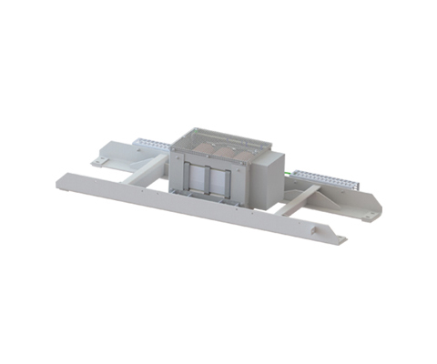
On-board power supply transformer for roof mounting Description The REO on-board power supply transformer NTT 400 D is designed for on-board power supplies that are fed by the on-board power converter (BNU). The transformer NTT 400 D refers to the complete, ready-to-operate unit with transformer, support frame, and housing. The transformer is used to adapt the voltage and for galvanic isolation of the pulse-width modulated DC link voltage and the loads of the electrical system. A corresponding sine filter must be connected between the transformer and the inverter. The secondary-side load of the isolation transformer can be switching devices, rotating machines, resistive loads, and semiconductor power converter devices. The Transformers are designed for use in vehicles in AC or DC networks (in inverter mode) in the container. This ensures that Transformers from REO are optimally aligned for your application. The main focuses in our development are maximum service life, cost/benefit optimization, and safety. Customized complete solutions On-board power supply transformers can be custom-designed. Are you interested in this product? Please contact us! In addition to standardized components for use in converters, REO offers customized products – as a single component or as a complete solution in a container. The benchmark in railway technology is the availability and safety of passengers. Here, REO offers special solutions that are developed step by step in close cooperation with the customer. Benefits Vibration and shock tested according to DIN 61373 Cat 1 Class B High efficiency Low no-load losses Reduced stray field Low noise emission Weight-optimized High mechanical load capacity Cooling ON Pollution degree PD4 Various power classes Technical data Rated power: 10000 – 30000 VA Input voltage: 3×440 V Power: 10-30 kVA Nominal voltage: Primary: Rated voltage: (Normal operation): 3×440 Veff 60 Hz Rated voltage: (External supply): 3×400 Veff 50 Hz Rated voltage: (Reduced operation): 3×345 Veff 47 Hz Secondary: Voltage: 3×230 Veff Operating temp.: -25°C … +55°C (optional +75°C) Humidity: max 95% Pollution degree: PD4 Insulation class: F/H Test voltage: EN 50124 / EN 60310 Vibration resistance: Cat.1 Class A/B according to EN61373 Voltages: 24 / 42 / 110 / 230 / 400 / 690 Volt (Optional) Switching group: Optional Type Power [kVA] Total weight [kg] Copper weight [kg] Efficiency [%] UK [%]* NTT 400 U/15.0 15.0 96 29 97.1 2.6 NTT 400 U/20.0 20.0 126 36 97.4 2.3 NTT 400 U/25.0 25.0 150 51 97.5 2.5 NTT 400 U/30.0 30.0 175 57 97.8 2.1 Dimensions in mm Type L W H N1 N2 N3 D Mass [kg] NTT 400 U/15.0 1800 581 376 1717 363 65 13×26 192 NTT 400 U/20.0 1800 581 376 1717 363 65 13×26 219 NTT 400 U/25.0 1800 581 376 1717 363 65 13×26 247 NTT 400 U/30.0 1800 581 376 1717 363 65 13×26 267