
Sinusoidal Filter CNW 931
Smoothing of the current and voltage in order to realize long connecting paths.
Sine wave filter N CNW 933
The new series not only scores points for its faster delivery time, but also for its resource conservation and increased efficiency.
Motor Choke N CNW 854

Three-phase motor choke Description Compact & Efficient The new series not only scores points for its faster delivery time, but also for its resource conservation and increased efficiency. Reduce voltage rise (< 200V / µs) and distortions – optimally protect electrical consumers. In addition to voltage rises, there is a considerable amount of symmetrical and asymmetrical current distortions generated at the motor supply line due to the rapid switching of power semiconductors. These become more pronounced with increasing cable length. These disturbances can affect the motor’s performance through loud noises and, in extreme cases, through overheating. A motor choke can provide a remedy here. The motor choke reduces the voltage rise and voltage peaks between the conductors. Furthermore, the current is smoothed. Losses and heating are minimized and leakage current is reduced. Longer motor cable lengths can be used. The motor insulation is protected, thus increasing its lifespan. The motor choke also dampens conducted interference in the lower frequency range very well. Losses and typical noises in the motor laminations are reduced. Voltage rises are reduced to (< 200V / µs.) Increasing the service life of motors, lowering the edge steepness du / dt to earth and between the phases, reducing motor noise, and current smoothing. Benefits Protection for electrical consumers Limitation of voltage rise to < 200V/µs extended service life for electrical consumers Reduction of motor noises low leakage currents on the motor longer motor cables possible Easy construction compact design Production according to UL insulation system E251513 possible Typical application Drive systems for motor drives, Mechanical engineering, Elevators / escalators, Pipes, Conveyor technology, Ventilation and air conditioning, Robotics, Automation technology, Power supplies, Wind turbines Technical data Reduction of voltage rise du/dt to < 200V/µs Field frequency: 0 – 60 Hz Drive Switching frequency of the inverter: up to 150 A >4kHz, from 150 A >1.5kHz According to: EN 60289 / EN 61558 Test voltage: L-L 2500 V, AC/50Hz 60s; L-PE 2500 V, AC/50Hz 60s Insulation class: T40/F Protection class: IP00 Climate category: DIN IEC 60068-1 Overload: 1.5 x INominal 1 min / h Ambient temperature: 40 °C Design: standing on foot bracket Technical data Type Nominal voltage U [V] Nominal current I [A] Inductance L [mH] Losses P [W] Mass [kg] Mass Cu [kg] Mass Al [kg] N CNW 854 / 2 500 50 / 60 Hz 2 7,00 21 1,0 0,3 – N CNW 854 / 4 4 3,60 26 1,1 0,5 – N CNW 854 / 8 8 2,00 35 2,0 0,5 – N CNW 854 / 10 10 1,70 44 2,2 0,9 – N CNW 854 / 12 12 1,20 52 2,7 0,8 – N CNW 854 / 16 16 0,90 54 2,8 0,9 – N CNW 854 / 24 24 0,70 55 4,4 1,9 – N CNW 854 / 30 30 0,50 40 4,5 0,9 – N CNW 854 / 37 37 0,42 40 6,0 1,4 – N CNW 854 / 48 48 0,32 60 7,0 1,9 – N CNW 854 / 60 60 0,28 80 7,0 2,0 – N CNW 854 / 75 75 0,22 100 8,0 1,4 – N CNW 854 / 90 90 0,17 80 10,0 1,9 – N CNW 854 / 115 115 0,14 150 14,0 1,6 – N CNW 854 / 150 150 0,11 170 16,0 3,1 – N CNW 854 / 180 180 0,09 160 18,0 3,2 – N CNW 854 / 200 200 0,08 170 23,0 2,8 – N CNW 854 / 250 250 0,065 240 24,0 3,8 – N CNW 854 / 300 300 0,053 380 44,0 1,5 2,7 N CNW 854 / 350 350 0,046 330 55,0 2,6 4,6 N CNW 854 / 400 400 0,041 380 58,0 2,6 4,9 N CNW 854 / 500 500 0,032 520 63,0 2,6 5,2 N CNW 854 / 600 600 0,028 650 65,0 5,0 5,9 N CNW 854 / 700 700 0,024 820 86,0 5,0 5,7 N CNW 854 / 800 800 0,021 710 108,0 6,6 9,0 N CNW 854 / 900 900 0,018 800 114,0 13,8 7,6 N CNW 854 / 1000 1000 0,016 900 114,0 13,8 7,6 N CNW 854 / 1200 1200 0,013 1170 122,0 13,8 8,0 DIMENSIONS IN MM Type Length L1 [mm] Length L2 [mm] Width B1 [mm] Width B2 [mm] High max. H1 [mm] Fastening N1 [mm] Fastening N2 [mm] Fastening D1 [mm x mm] Clamp/ cable lug [mm²] Angle [mm x mm] Port A1 [mm] Port D2 [mm] PE Ø [mm] N CNW 854 / 2 80 96 45 55 110 56 34 5 x 8 2.5 – – – M4 N CNW 854 / 4 80 96 45 55 110 56 34 5 x 8 2.5 – – – M4 N CNW 854 / 8 80 96 55 65 110 56 43 5 x 8 2.5 – – – M4 N CNW 854 / 10 125 120 61 66 130 100 45 5 x 8 2.5 – – – M4 N CNW 854 / 12 125 120 71 67 130 100 55 5 x 8 2.5 – – – M4 N CNW 854 / 16 125 120 71 67 130 100 55 5 x 8 2.5 – – – M4 N CNW 854 / 24 155 150 76 86 170 130 54 8 x 12 10 – – – M4 N CNW 854 / 30 155 – 110 130 130 54 8 x 12 16 (M6) – 40 – M6 N CNW 854 / 37 155 – 125 130 130 69 8 x 12 16 (M6) – 40 – M6 N CNW 854 / 48 190 – 115 165 170 57 57 8 x 12 16 (M8) – 40 – M8 N CNW 854 / 60 190 – 115 165 170 57 57 8 x 12 16 (M8) – 40 – M8 N CNW 854 / 75 190 – 135 160 170 67 67 8 x 12 16 (M8) – 40 – M8 N CNW 854 / 90 190 – 135 160 170 77 77 8 x 12 16
du/dt Drossel N CNW 806
Three-phase dv/dt filter Description NEW SERIES! The new series not only scores points for its faster delivery time, but also for its resource conservation and increased efficiency. Reduce voltage rise to < 500V / µs – protect electrical loads and insulation cost-effectively. A simple and cost-effective method to reduce the voltage rise rate is to use a du/dt Drossel or filter. It dampens the voltage rise to tolerable levels and prevents overvoltages on long supply lines. Losses and heating are minimized, and the leakage current is reduced. By limiting the voltage steepness, the motor insulation is protected, thus extending its service life. EMC interference in the radiation range from 1 MHz to 30 MHz is also reduced. Benefits Protection for electrical consumers Limitation of voltage rise to < 500V / µs extended service life for electrical consumers low leakage currents on the motor Reduced losses Easy construction compact design Production according to UL insulation system E251513 possible Typical application Drive systems for motor drives, Mechanical engineering, Elevators / escalators, Pipes, Conveyor technology, Ventilation and air conditioning, Robotics, Automation technology, Power supplies, Wind turbines Technical data Rated voltage: U ≤ 3 x 500 V Reduction of voltage rise du/dt to < 500V/µs Field frequency: 0 – 60 Hz Drive Switching frequency of the inverter: up to 150 A >4kHz, from 150 A >1.5kHz According to: EN 60289 / EN 61558 Test voltage: L-L 2500 V, AC/50Hz 60s; L-PE 2500 V, AC/50Hz 60s Insulation class: T40/F Protection class: IP00 Climate category: DIN IEC 60068-1 Overload: 1.5 x INominal 1 min / h Ambient temperature: 40 °C Design: standing on foot bracket Technical data Type Nominal voltage U [V] Nominal current I [A] Inductance L [mH] Resistance R [mΩ] Losses P [W] UK at 400 V, 50 Hz [%] UK at 230 V, 50 Hz [%] UK at 480 V, 60 Hz [%] UK at 500 V, 50 Hz [%] Mass [kg] Mass Cu [kg] Mass Al [kg] N CNW 806 / 4 500 50 / 60 Hz 4 1,500 92,7 10 0,8 1,4 0,8 0,7 1,0 0,12 N CNW 806 / 10 500 50 / 60 Hz 10 0,600 26,4 20 0,8 1,4 0,8 0,7 2,0 0,15 N CNW 806 / 18 500 50 / 60 Hz 18 0,330 12,0 20 0,8 1,4 0,8 0,6 2,0 0,21 N CNW 806 / 24 500 50 / 60 Hz 24 0,245 9,1 30 0,8 1,4 0,8 0,6 2,5 0,24 N CNW 806 / 37 500 50 / 60 Hz 37 0,160 4,8 30 0,8 1,4 0,8 0,6 3,0 0,57 N CNW 806 / 48 500 50 / 60 Hz 48 0,123 2,7 40 0,8 1,4 0,8 0,6 3,0 0,45 N CNW 806 / 65 500 50 / 60 Hz 65 0,090 2,0 50 0,8 1,4 0,8 0,6 4,0 0,57 N CNW 806 / 90 500 50 / 60 Hz 90 0,065 1,5 60 0,8 1,4 0,8 0,6 5,0 0,72 N CNW 806 / 120 500 50 / 60 Hz 120 0,050 1,1 80 0,8 1,4 0,8 0,7 7,0 1,44 N CNW 806 / 150 500 50 / 60 Hz 150 0,039 0,5 60 0,8 1,4 0,8 0,6 8,0 1,65 N CNW 806 / 180 500 50 / 60 Hz 180 0,033 0,5 80 0,8 1,4 0,8 0,6 9,0 1,35 N CNW 806 / 200 500 50 / 60 Hz 200 0,029 0,5 100 0,8 1,4 0,8 0,6 9,0 1,50 N CNW 806 / 250 500 50 / 60 Hz 250 0,024 0,22 120 0,8 1,4 0,8 0,7 15,0 1,10 1,50 N CNW 806 / 300 500 50 / 60 Hz 300 0,020 0,15 140 0,8 1,4 0,8 0,7 16,0 1,10 2,55 N CNW 806 / 350 500 50 / 60 Hz 350 0,017 0,13 140 0,8 1,4 0,8 0,6 21,0 6,5 N CNW 806 / 400 500 50 / 60 Hz 400 0,015 0,10 150 0,8 1,4 0,8 0,7 24,0 2,2 2,25 N CNW 806 / 500 500 50 / 60 Hz 500 0,012 0,10 200 0,8 1,4 0,8 0,7 27,0 2,60 3,30 N CNW 806 / 600 500 50 / 60 Hz 600 0,010 0,08 250 0,8 1,4 0,8 0,7 32,0 4,40 2,55 N CNW 806 / 700 500 50 / 60 Hz 700 0,008 0,07 260 0,8 1,3 0,8 0,6 35,0 4,90 3,00 N CNW 806 / 800 500 50 / 60 Hz 800 0,007 0,06 280 0,8 1,3 0,8 0,6 36,0 5,20 3,90 N CNW 806 /900 500 50 / 60 Hz 900 0,0065 0,05 290 0,8 1,4 0,8 0,6 55,0 10,8 5,55 N CNW 806 / 1000 500 50 / 60 Hz 1000 0,006 0,05 360 0,8 1,4 0,8 0,7 56,0 10,8 5,85 N CNW 806 / 1200 500 50 / 60 Hz 1200 0,005 0,05 480 0,8 1,4 0,8 0,7 56,0 10,8 6,00 DIMENSIONS IN MM Type Length Width High max. Mounting Terminal/ cable lug [mm²] Connection L1 [mm] L2 [mm] B1 [mm] B2 [mm] H1 [mm] N1 [mm] N2 [mm] D1 [mm x mm] Angle [mm x mm] A1 [mm] D2 [mm] PE Ø [mm] N CNW 806 / 4 65 78 50 60 95 50 38 5 x 8 2,5 – – – M4 N CNW 806 / 10 80 96 45 55 110 65 34 5 x 8 2,5 – – – M4 N CNW 806 / 18 80 96 5 65 110 65 43 5 x 8 2,5 – – – M4 N CNW 806 / 24 125 120 61 76 145 100 45 5 x 8 10 – – – M4 N CNW 806 / 37 125 – 90 – 105 100 45 5 x 8 10 (M6) – 40 – M6 N CNW 806 / 48 125 – 100 – 105 100 55 5 x 8 10 (M6) – 40 – M6 N CNW 806 / 65 155 – 110 – 130 130 54 8 x 12 16 (M8) – 40 – M6 N CNW 806 / 90 155 – 120 – 130 130 69 8 x 12 16 (M8) – 40
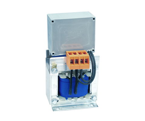
DC-Link Choke N CNW 892
DC-link chokes (2 lines) Description Compact & Efficient Reduce mains interference – save energy costs. The DC link choke is used to smooth the DC link current and reduce mains feedback in voltage DC link converters. The typical combinations of rectifiers and capacitors place a considerable load on the supply network. Due to its function, the current consumption of the power supplies or converters is not sinusoidal, but pulse-shaped at the moment of the voltage maximum. DC link chokes reduce the harmonics and relieve the supply network in a similar way to the mains choke. In addition, the DC link choke dampens the charging current peaks of the DC link capacitors. A DC link choke reduces the burden on the supply network with harmonic reactive power. Improvement of the efficiency of a converter (Power Factor Correction). Inrush currents and current peaks are damped by up to 70%. Mains chokes help to comply with the international PowerQuality standards IEEE 519 or EN 61000-3-2. Benefits Reduction of harmonic overtones Damping of current peaks up to 70% compact design Advantages compared to the mains choke: smaller size lower material costs / price lower power dissipation Production according to UL insulation system E251513 possible Typical application Drive systems for motor drives, Mechanical engineering, Elevators / escalators, Pipes, Conveyor technology, Ventilation and air conditioning, Robotics, Automation technology, Power supplies, Wind turbines Technical data Rated voltage: U ≤ 800 V According to: EN 60289 / EN 61558 Test voltage: L-PE 4000 V, AC/50Hz, 60s Insulation class: T40/F Protection class: IP00 Climate category: DIN IEC 60068-1 Overload: 1.5 x INominal 1 min / h Design: standing on foot bracket Technical Data Type Nominal voltage U [V] Nominal current I [A] Inductance L [mH] Losses P [W] Mass [kg] Mass Cu [kg] N CNW 892 / 8 600 50 / 60 Hz 8 9,4 30 1,4 0,6 N CNW 892 / 11 600 50 / 60 Hz 11 6,2 30 2,0 0,6 N CNW 892 / 15 600 50 / 60 Hz 15 4,8 40 2,4 0,8 N CNW 892 / 20 800 50 / 60 Hz 20 3,3 30 3,0 1,2 N CNW 892 / 28 800 50 / 60 Hz 28 2,4 40 3,8 2,1 N CNW 892 / 34 800 50 / 60 Hz 34 2,0 40 4,0 1,3 N CNW 892 / 40 800 50 / 60 Hz 40 1,6 70 5,0 1,2 N CNW 892 / 55 800 50 / 60 Hz 55 1,2 80 6,0 1,4 N CNW 892 / 70 800 50 / 60 Hz 70 0,98 80 8,0 2,3 N CNW 892 / 85 800 50 / 60 Hz 85 0,81 90 11,0 2,0 N CNW 892 / 100 800 50 / 60 Hz 100 0,67 120 13,0 1,8 DIMENSIONS IN MM Type Dimensions L (mm) Dimensions B (mm) Dimensions H (mm) Mounting N1 (mm) Mounting N2 (mm) Mounting D1 (mm) Terminal connection/Cable lug[mm²] PE connection Connection A1 (mm) Image N CNW 892 / 8 80 53 135 50 39 4,8 x 9 4,0 M4 1 N CNW 892 / 11 80 63 135 50 49 4,8 x 9 4,0 M4 1 N CNW 892 / 15 100 66 155 63 49 6 x 10 4,0 M4 1 N CNW 892 / 20 100 66 140 63 49 6 x 10 10 (M4) M4 35 2 N CNW 892 / 28 100 81 140 63 64 6 x 10 10 (M5) M4 35 2 N CNW 892 / 34 100 81 140 63 64 6 x 10 16 (M5) M4 35 2 N CNW 892 / 40 120 87,5 165 76 68,5 7 x 13 10 (M6) M6 40 3 N CNW 892 / 55 120 97,5 165 76 78,5 7 x 13 16 (M6) M6 40 3 N CNW 892 / 70 152 92 205 100 73 7 x 13 25 (M8) M8 45 3 N CNW 892 / 85 152 112 205 100 93 7 x 13 25 (M8) M8 45 3 N CNW 892 / 100 160 127 215 100 103 7 x 13 25 (M8) M8 45 3 Datasheet All data and configurations can be found in our product datasheet. Download Datasheet Certifications
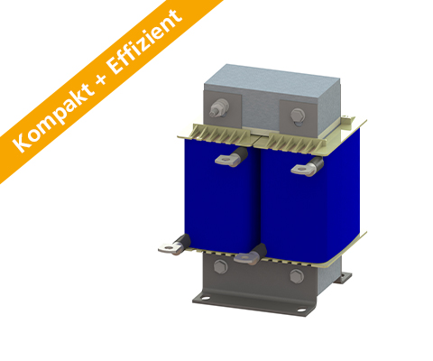
DC-Link reactor N CNW 891
Single-phase DC-link reactor (1 line) DESCRIPTION Power Noise Reduction – save energy costs. The DC-link reactor is used for smoothing the DC link current and to reduce mains harmonics in voltage source inverters. The typical combinations of rectifiers and capacitors strains the supply network significantly. For functional reasons, the current consumption of the power supply or the inverter is not sinusoidal but pulsed at the moment of maximum voltage. DC-link reactor reduce the harmonics and relieve the supply network similar to the mains choke. In addition, the DC-link reactor attenuates charging current peak surges of the DC-link capacitors. By using a DC-link reactor the supply network is less burdened with harmonic reactive power. Improvement of the efficiency of a converter (Power Factor Correction). Starting currents and current peak are attenuated up to 70%. Line reactors help to comply with international power quality standards IEEE 519 or EN 61000-3-2. TYPICAL APPLICATIONS Drive systems for motor drives,Mechanical engineering,Elevators/ escalators,Pipes,Conveyor technology,Ventilation and air conditioning,Robotics,Automation technology,Power supplies,Wind turbines ADVANTAGES Reduction of harmonics waves Attenuation of current spikes of up to 70% Compact design Advantages over line reactor: Smaller size Lower cost of materials / Price Smaller power loss Production possible according to UL insulation system E251513 Technical Data Nominal voltage: U ≤ 600 V According to: EN 60289 / EN 61558 Test voltage: L-PE 4000 V, AC/50Hz, 60s Insulation class: T40/F Protection rating: IP00 Climatic category: DIN IEC 60068-1 Overload: 1,5 x INenn 1 min / h Design: standing on foot angle TECHNICAL SPECIFICATION Type Nominal voltage U [V] Nominal current [A] Inductance [mH] Power dissipation [W] Mass[kg] [kg] Weight Cu [kg] N CNW 891 / 8 600 50 / 60 Hz 8 9,4 14 1,4 0,3 N CNW 891 /11 600 50 / 60 Hz 11 6,2 15 2 0,3 N CNW 891 / 15 600 50 / 60 Hz 15 4,8 20 2,8 0,6 N CNW 891 / 20 800 50 / 60 Hz 20 3,3 19 3,6 0,6 N CNW 891 /28 800 50 / 60 Hz 28 2,4 22 3,6 0,8 N CNW 891 / 34 800 50 / 60 Hz 34 2,0 29 4,5 0,8 N CNW 891 / 40 800 50 / 60 Hz 40 1,6 31 7 1 N CNW 891 / 55 800 50 / 60 Hz 55 1,2 43 8 1,2 N CNW 891 / 70 800 50 / 60 Hz 70 0,98 49 10,5 1,4 N CNW 891 / 85 800 50 / 60 Hz 85 0,81 60 13,6 1,8 N CNW 891 / 100 800 50 / 60 Hz 100 0,67 70 14 2,5 DIMENSIONS IN MM Type Lenght L1 (mm) Broad B1 (mm) Broad B2 (mm) High max. H (mm) Mounting N1 (mm) Attachment N2 (mm) Attachment D1 (mm x mm) Terminal connection/ cable lug [mm²] Connection PE Connection A1 (mm) Design N CNW 891 / 8 84 76 62 80 64 48 5 x 8 2,5 Flat plug 6,3 x 0,8 1 N CNW 891 /11 84 90 76 80 64 62 5 x 8 2,5 Flat plug 6,3 x 0,8 1 N CNW 891 / 15 96 95 88 85 84 72 6 x 11 2,5 Flat plug 6,3 x 0,8 1 N CNW 891 / 20 96 138 102 85 84 85 6 x 11 10 (m5) M5 40 2 N CNW 891 /28 96 138 102 85 84 85 6 x 11 16 (M5) M5 40 2 N CNW 891 / 34 105 138 105 95 84 87 6 x 11 16 (M5) M5 40 2 N CNW 891 / 40 120 155 120 105 90 105 6 x 11 16 (M5) M6 45 2 N CNW 891 / 55 150 138,5 107,5 135 122 87,5 7 x 13 16 (M5) M6 45 2 N CNW 891 / 70 150 159 124,5 135 122 104,5 7 x 13 25 (M8) M6 45 2 N CNW 891 / 85 150 185,5 150,5 135 122 130,5 7 x 13 25 (M8) M6 45 2 N CNW 891 / 100 174 162,5 121 150 135 101 7 x 13 35 (M8) M8 50 2 Data sheet Download our extensive catalog and discover many other REO products. Download Datenblatt Certifications
Liquid-cooled choke MD 953

Liquid-cooled three-phase mains choke 8% Uk Description Water-cooled Chokes are available in IP protection classes from IP00 to IP65. REO offers various types of water cooling for these components. The targeted dissipation of losses via the cooling circuit prevents their transfer to the environment. By using water cooling, component temperatures can be significantly reduced – this means less stress on insulation materials and an extended service life. REO’s special technology enables excellent heat distribution, thus preventing the formation of so-called hot spots. Benefits Protection class up to IP 65 Longer lifetime Optimal heat dissipation Suitable for railway applications Technical data Insulation class: F Cooling medium: water/glycol (other cooling liquids on request) Max. Coolant inlet temperature: 50° C Rated voltage : 400 V Rated Current: 200 – 1200 A Inductance: 0.012 – 0.074 mH Technical data Type Rated voltage [V] Rated current [A] Uk Linear up to Inductance [μH] R20 [mΩ] Winding weight [kg] NTT MD 953/200 3 x 400 (optional 3×690) 200 8% 300 74 2,1 7 NTT MD 953/400 3 x 400 (optional 3×690) 400 8% 600 37 0,96 11 NTT MD 953/600 3 x 400 (optional 3×690) 600 8% 900 25 0,49 15 NTT MD 953/800 3 x 400 (optional 3×690) 800 8% 1200 18 0,4 19 NTT MD 953/1000 3 x 400 (optional 3×690) 1000 8% 1500 15 0,3 18 NTT MD 953/1200 3 x 400 (optional 3×690) 1200 8% 1800 12 0,18 32
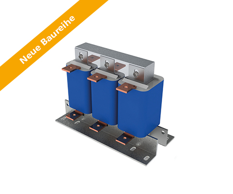
Mains chokes N CNW 905
Three-phase line reactor 2% Uk Description Compact & Efficient The new series not only scores points for its faster delivery time, but also for its resource conservation and increased efficiency. Power Noise Reduction – save up to 15% energy costs. A line reactor relieves the supply network by compensating the harmonics reactive power. The harmonics and commutation notches are reduced strongly. By using a line reactor the inverter electronics and DC-capacitors will be protected. Starting currents and current peaks are reduced up to 30%. Mains chokes help to comply with the international PowerQuality standards IEEE 519 or EN 61000-3-2. Benefits compact design extended service life for electrical consumers Low-temperature rise Attenuation of current spikes up to 30% Reduction of input current up to 15% Low-noise Production according to UL insulation system E251513 possible Typical applications Drive systems for motor drives: Mechanical engineering, Elevators / escalators, Pipes, Conveyor technology, Ventilation and air conditioning, Robotics, Automation technology, Power supplies and Wind turbines Technical data Rated voltage: U ≤ 3 x 500 V Short circuit: Uk 2% (400VAC/50Hz, INenn) Frequency: 50/60 Hz According to: EN 60289 / EN 61558 Test voltage: LL 2500 V, DC 1min; L-PE 2500 V, DC 1min Insulation class: T40/F Protection class: IP00 Climate category: DIN IEC 60068-1 Overload: 1.5 x INominal 1 min / h Design: standing on foot bracket Technical data Type Nominal voltage / nominal frequency UN [V] Nominal current IN [A] Inductance L [mH] Losses P [W Weight [kg Mass Cu [kg] Mass Al [kg] N CNW 903 /3 500 50 / 60 Hz 3 9,800 16 1.0 0.2 – N CNW 903 /6 500 50 / 60 Hz 6 4,880 25 2.0 0.3 – N CNW 903 /8 500 50 / 60 Hz 8 3,680 35 2.0 0.3 – N CNW 903 /10 500 50 / 60 Hz 10 2,930 36 3.0 0.4 – N CNW 903 /12 500 50 / 60 Hz 12 2,450 38 3.0 0.45 – N CNW 903 /16 500 50 / 60 Hz 16 1,830 48 4.0 0.7 – N CNW 903 /25 500 50 / 60 Hz 25 1,170 63 5.2 0.8 – N CNW 903 /36 500 50 / 60 Hz 36 0,810 67 7.0 1.9 – N CNW 903 /50 500 50 / 60 Hz 50 0,590 112 9.0 1.2 – N CNW 903 /70 500 50 / 60 Hz 70 0,420 180 11 2.1 – N CNW 903 /90 500 50 / 60 Hz 90 0,330 144 17 2.5 – N CNW 903 /110 500 50 / 60 Hz 110 0,270 179 18 1.8 – N CNW 903 /125 500 50 / 60 Hz 125 0,235 220 17 2.6 – N CNW 903 /160 500 50 / 60 Hz 160 0,180 145 22 5.0 – N CNW 903 /200 500 50 / 60 Hz 200 0,147 187 26 1.3 3.8 N CNW 903 /250 500 50 / 60 Hz 250 0,118 254 35 1.3 3.0 N CNW 903 /300 500 50 / 60 Hz 300 0,098 250 37 1.3 4.7 N CNW 903 /350 500 50 / 60 Hz 350 0,084 267 45 2.6 5.0 N CNW 903 /400 500 50 / 60 Hz 400 0,074 365 52 2.6 5.2 N CNW 903 /500 500 50 / 60 Hz 500 0,059 423 58 2.9 7.8 N CNW 903 /600 500 50 / 60 Hz 600 0,049 450 71 5.0 6.9 N CNW 903 /700 500 50 / 60 Hz 700 0,042 493 88 5.0 9.2 N CNW 903 /800 500 50 / 60 Hz 800 0,037 545 96 5.1 8.3 N CNW 903 /900 500 50 / 60 Hz 900 0,033 655 108 12.5 10.1 N CNW 903 /1000 500 50 / 60 Hz 1000 0,029 775 108 12.5 10.1 N CNW 903 /1200 500 50 / 60 Hz 1200 0,024 1009 133 13.9 12.4 Dimensions in mm Type Length L1 (mm) Lenght L2 (mm) Width B1 (mm) Width B2 (mm) High max. H1 (mm) Mounting N1 (mm) Mounting N2 (mm) Mounting D1 (mm x mm) Terminal/ Cable lug [mm²] Angle [mm x mm] Connection A1 (mm) Connetion D2 (mm) PE N CNW 903 /3 65 78 50 60 95 50 38 5 x 8 2.5 M4 N CNW 903 /6 80 96 55 65 110 56 43 5 x 8 2.5 M4 N CNW 903 /8 125 120 61 66 130 100 45 5 x 8 2.5 M4 N CNW 903 /10 125 120 71 76 130 100 55 5 x 8 2.5 M4 N CNW 905 /12 125 120 71 76 130 100 55 5 x 8 2.5 M4 N CNW 903 /16 155 150 76 76 155 130 54 8 x 12 2.5 M4 N CNW 903 /25 155 150 91 101 170 130 69 8 x 12 10 M4 N CNW 903/36 190 180 81 91 195 170 57 8 x 12 10 M6 N CNW 903 /50 190 180 101 111 195 170 77 8 x 12 10 M6 N CNW 903 /70 230 136 200 176 73 9 x 13 16 (M8) 45 M8 N CNW 903 /90 230 150 200 176 95 9 x 13 16 (M8) 45 M8 N CNW 905 /110 240 150 210 185 97 10 x 18 16 (M8) 45 M8 N CNW 905 /125 240 150 210 185 95 10 x 18 45 M8 N CNW 903 /160 240 175 210 185 103 10 x 18 35 (M10) 55 M8 N CNW 903 /200 300 148 270 224 95 10 x 18 30 x 4 39 11 M12 N CNW 903 /250 300 184 270 224 125 10 x 18 30 x 4 39 11 M12 N CNW 903 /300 300 190 270 224 125 10 x 18 30 x 4 39 11 M12 N CNW 903 /350 340 192 305 248 130 10 x 18 40 x 5 49 13 M12 N CNW 903 /400 360 195 315 264 142 10 x 18 40 x 5 49 13 M12 N CNW
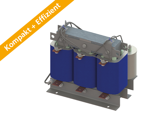
Mains choke N CNW 903

Three-phase line reactor 4% Uk Description Compact & Efficient The new series not only scores points for its faster delivery time, but also for its resource conservation and increased efficiency. Reduce mains interference – save up to 20% on energy costs. A mains choke relieves the supply network by compensating for harmonic reactive power. The harmonics and commutation dips are greatly reduced. The use of a mains choke protects the inverter electronics and the DC link capacitors. Starting currents and current peaks are reduced up to 60%. Line reactors help to comply with international power quality standards IEEE 519 or EN 61000-3-2. Benefits compact design extended service life for electrical consumers Low-temperature rise Attenuation of current spikes up to 60% Reduction of input current up to 20% Low-noise Production according to UL insulation system E251513 possible Typical application Drive systems for motor drives, Mechanical engineering, Elevators / escalators, Pipes, Conveyor technology, Ventilation and air conditioning, Robotics, Automation technology, Power supplies, Wind turbines Technical data Rated voltage: U ≤ 3 x 500 V Short circuit: Uk 4% (400VAC/50Hz, INenn) Frequency: 50/60 Hz According to: EN 60289 / EN 61558 Test voltage: L-L 2500 V, DC 1min; L-PE 2500 V, DC 1min Insulation class: T40/F Protection rating: IP 00 Climate category: DIN IEC 60068-1 Overload: 1,5 x INenn 1 min / h Design: standing on foot bracket Technical data Type Nominal voltage / nominal frequency UN [V] Nominal current IN [A] Inductance L [mH] Losses P [W] Mass [kg] Weight Cu [kg Mass Al [kg] N CNW 903 /3 500 50 / 60 Hz 3 9,800 16 1,0 0,2 N CNW 903 /6 500 50 / 60 Hz 6 4,880 25 2,0 0,3 N CNW 903 /8 500 50 / 60 Hz 8 3,680 35 2,0 0,3 N CNW 903 /10 500 50 / 60 Hz 10 2,930 36 3,0 0,4 N CNW 903 /12 500 50 / 60 Hz 12 2,450 38 3,0 0,5 N CNW 903 /16 500 50 / 60 Hz 16 1,830 48 4,0 0,7 N CNW 903 /25 500 50 / 60 Hz 25 1,170 63 5,2 0,8 N CNW 903 /36 500 50 / 60 Hz 36 0,810 67 7,o 1,9 N CNW 903 /50 500 50 / 60 Hz 50 0,590 112 9 1,2 N CNW 903 /70 500 50 / 60 Hz 70 0,420 180 11 2,1 N CNW 903 /90 500 50 / 60 Hz 90 0,330 144 17 2,5 N CNW 903 /110 500 50 / 60 Hz 110 0,270 179 18 2,8 N CNW 903 /125 500 50 / 60 Hz 125 0,235 220 17 2,6 N CNW 903 /160 500 50 / 60 Hz 160 0,180 145 22 5,0 N CNW 903 /200 500 50 / 60 Hz 200 0,147 187 26 1,3 3,8 N CNW 903 /250 500 50 / 60 Hz 250 0,118 254 35 1,3 3,0 N CNW 903 /300 500 50 / 60 Hz 300 0,098 250 37 1,3 4,7 N CNW 903 /350 500 50 / 60 Hz 350 0,084 267 45 2,6 5,0 N CNW 903 /400 500 50 / 60 Hz 400 0,074 365 52 2,6 5,2 N CNW 903 /500 500 50 / 60 Hz 500 0,059 423 58 2,9 7,8 N CNW 903 /600 500 50 / 60 Hz 600 0,049 450 71 5,0 6,9 N CNW 903 /700 500 50 / 60 Hz 700 0,042 493 88 5,0 9,2 N CNW 903 /800 500 50 / 60 Hz 800 0,037 545 96 5,1 8,3 N CNW 903 /900 500 50 / 60 Hz 900 0,033 655 108 12,5 10,1 N CNW 903 /1000 500 50 / 60 Hz 1000 0,029 775 108 12,5 10,1 N CNW 903 /1200 500 50 / 60 Hz 1200 0,024 1009 133 13,9 12,4 DIMENSIONS IN MM Type Length L1 (mm) Lenght L2 (mm) Width B1 (mm) Width B2 (mm) High max. H1 (mm) Mounting N1 (mm) Mounting N2 (mm) Mounting D1 (mm x mm) Terminal/cable lug [mm²] Connection Angle (mm x mm) Connection A1 (mm) Connetion D2 (mm) PE connection N CNW 903 /3 65 78 50 60 95 50 38 5 x 8 2,5 M4 N CNW 903 /6 80 96 55 65 110 56 43 5 x 8 2,5 M4 N CNW 903 /8 125 120 61 66 130 100 45 5 x 8 2,5 M4 N CNW 903 /10 125 120 71 76 130 100 55 5 x 8 2,5 M4 N CNW 903 /12 125 120 71 76 130 100 55 5 x 8 2,5 M4 N CNW 903 /16 155 150 76 76 155 130 54 8 x 12 2,5 M4 N CNW 903 /25 155 150 91 101 170 130 69 8 x 12 10 M4 N CNW 903 /36 190 180 81 91 195 170 57 8 x 12 10 M6 N CNW 903 /50 190 130 160 170 77 8 x 12 16 (M6) 45 M6 N CNW 903 /70 230 136 200 176 73 9 x 13 16 (M8) 45 M8 N CNW 903 /90 230 150 200 176 95 9 x 13 16 (M8) 45 M8 N CNW 903 /110 240 150 210 185 97 10 x 18 16 (M8) 45 M8 N CNW 903 /125 240 150 210 185 95 10 x 18 16 (M8) 45 M8 N CNW 903 /160 240 175 210 185 103 10 x 18 35 (M10) 55 M8 N CNW 903 /200 300 148 270 224 95 10 x 18 30 x 4 39 11 M12 N CNW 903 /250 300 184 270 224 125 10 x 18 30 x 4 39 11 M12 N CNW 903 /300 300 190 270 224 125 10 x 18 30 x 4 39 11 M12 N CNW 903 /350 340 192 305 248 130 10 x 18 40 x 5 49 13 M12 N CNW 903 /400 360 195 315 264 142 10 x 18 40 x 5 49 13 M12 N CNW 903 /500 360 200 345 264
Mains choke N CNW 901

Reduce mains interference – save up to 20% on energy costs. A mains choke relieves the supply network by compensating for harmonic reactive power.