| Type | Nominal voltage U [V] |
Nominal current [A] |
Inductance [mH] |
Power dissipation [W] |
Mass [kg] |
Mass Cu [kg] |
| N CNW 891 / 8 | 600 50 / 60 Hz |
8 | 9,4 | 14 | 1,4 | 0,3 |
| N CNW 891 /11 | 600 50 / 60 Hz |
11 | 6,2 | 15 | 2 | 0,3 |
| N CNW 891 / 15 | 600 50 / 60 Hz |
15 | 4,8 | 20 | 2,8 | 0,6 |
| N CNW 891 / 20 | 800 50 / 60 Hz |
20 | 3,3 | 19 | 3,6 | 0,6 |
| N CNW 891 /28 | 800 50 / 60 Hz |
28 | 2,4 | 22 | 3,6 | 0,8 |
| N CNW 891 / 34 | 800 50 / 60 Hz |
34 | 2,0 | 29 | 4,5 | 0,8 |
| N CNW 891 / 40 | 800 50 / 60 Hz |
40 | 1,6 | 31 | 7 | 1 |
| N CNW 891 / 55 | 800 50 / 60 Hz |
55 | 1,2 | 43 | 8 | 1,2 |
| N CNW 891 / 70 | 800 50 / 60 Hz |
70 | 0,98 | 49 | 10,5 | 1,4 |
| N CNW 891 / 85 | 800 50 / 60 Hz |
85 | 0,81 | 60 | 13,6 | 1,8 |
| N CNW 891 / 100 | 800 50 / 60 Hz |
100 | 0,67 | 70 | 14 | 2,5 |
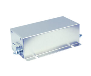
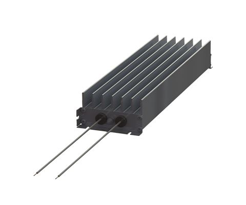
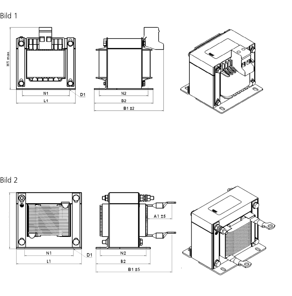
| Type | Length L1 (mm) | Width B1 (mm) | Width B2 (mm) | Height max. H (mm) | Mounting N1 (mm) | Mounting N2 (mm) | Mounting D1 (mm x mm) | Connection terminal/ cable lug [mm²] |
PE connection | Connection A1 (mm) | Image |
| N CNW 891 / 8 | 84 | 76 | 62 | 80 | 64 | 48 | 5 x 8 | 2,5 | Flat connector 6.3 x 0.8 | 1 | |
| N CNW 891 /11 | 84 | 90 | 76 | 80 | 64 | 62 | 5 x 8 | 2,5 | Flat connector 6.3 x 0.8 | 1 | |
| N CNW 891 / 15 | 96 | 95 | 88 | 85 | 84 | 72 | 6 x 11 | 2,5 | Flat connector 6.3 x 0.8 | 1 | |
| N CNW 891 / 20 | 96 | 138 | 102 | 85 | 84 | 85 | 6 x 11 | 10 (m5) | M5 | 40 | 2 |
| N CNW 891 /28 | 96 | 138 | 102 | 85 | 84 | 85 | 6 x 11 | 16 (M5) | M5 | 40 | 2 |
| N CNW 891 / 34 | 105 | 138 | 105 | 95 | 84 | 87 | 6 x 11 | 16 (M5) | M5 | 40 | 2 |
| N CNW 891 / 40 | 120 | 155 | 120 | 105 | 90 | 105 | 6 x 11 | 16 (M5) | M6 | 45 | 2 |
| N CNW 891 / 55 | 150 | 138,5 | 107,5 | 135 | 122 | 87,5 | 7 x 13 | 16 (M5) | M6 | 45 | 2 |
| N CNW 891 / 70 | 150 | 159 | 124,5 | 135 | 122 | 104,5 | 7 x 13 | 25 (M8) | M6 | 45 | 2 |
| N CNW 891 / 85 | 150 | 185,5 | 150,5 | 135 | 122 | 130,5 | 7 x 13 | 25 (M8) | M6 | 45 | 2 |
| N CNW 891 / 100 | 174 | 162,5 | 121 | 150 | 135 | 101 | 7 x 13 | 35 (M8) | M8 | 50 | 2 |
All data and configurations can be found in our product data sheet.